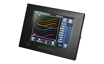
EDX-200A
Universal Recorder

  • CE
  • TEDS

EDX-200A

Summary

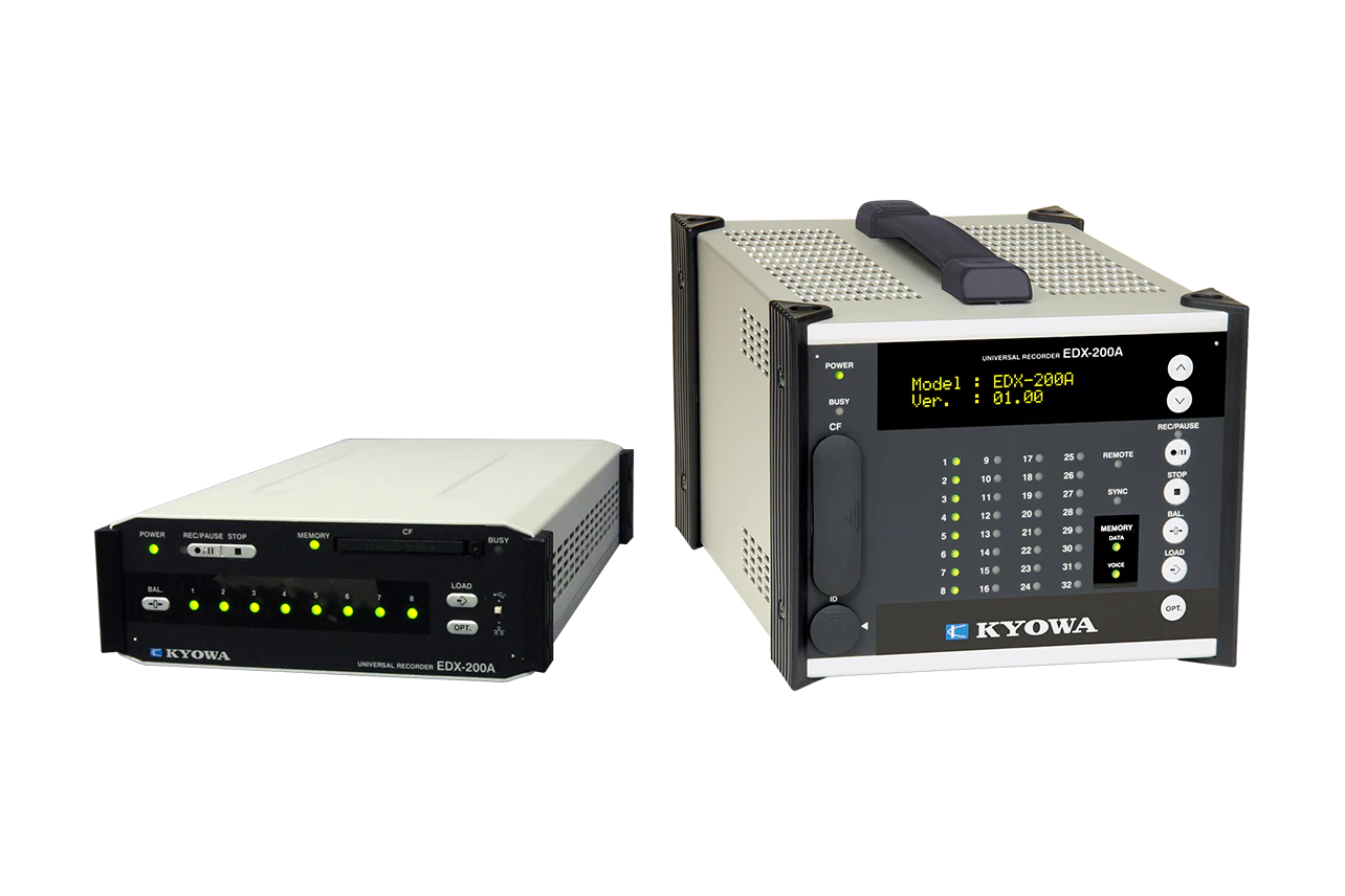
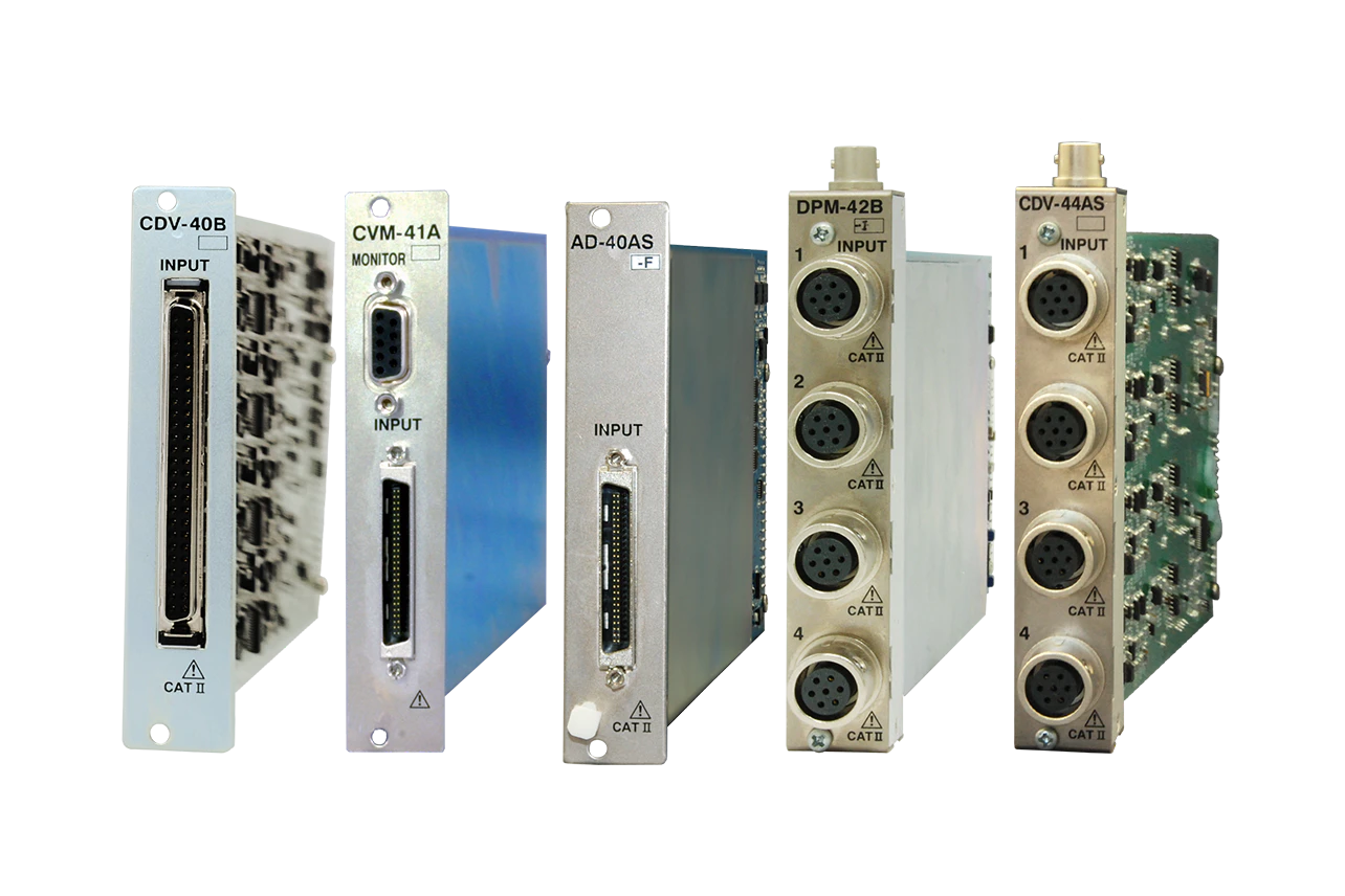
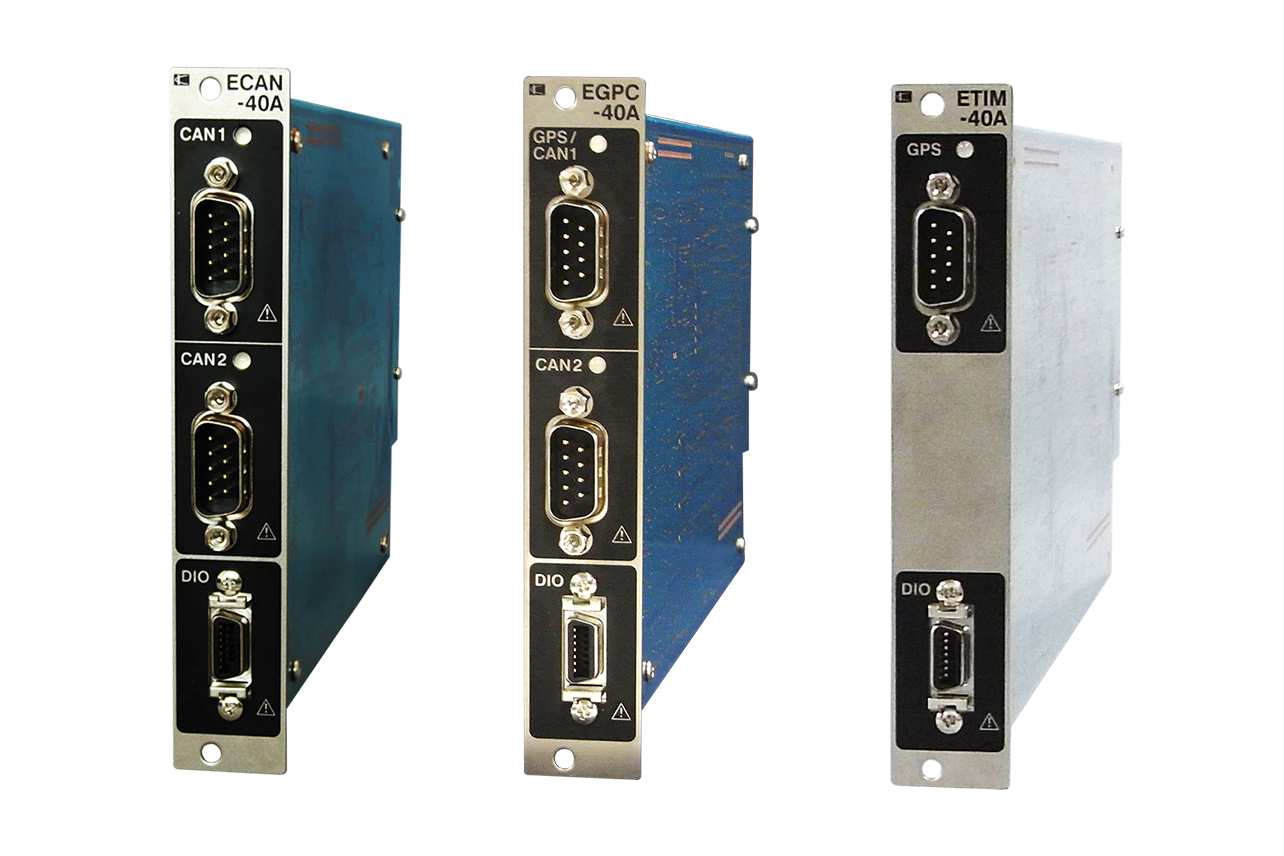
・Incorporated real-time digital filter.
 8th digital filter enables acquisition of clear waveform.
・High-speed/low-speed dual sampling
 Measurement of high-speed and low-speed phenomena while reducing data quantities is possible.
・All channels synchronous 10 kHz high-speed sampling (For 32 channels)
 Measurement of 3 channels synchronous at max. 100 kHz
・EDX-200A-4T can operate under high or low temperature range -20 to 65ºC
・One-wire synchronous (Except EDX-200A-1)
 With a maximum of 8 units, large scale measurements in distributed arrangement can be supported.

Features

The EDX-200A is a high-end Universal Recorder, which is as user-friendly as EDX-100A.
Various conditioner cards are available for wide applications.

Products table

All display

EDX-200A-1
Max. 8 channels, 1 slot

EDX-200A-1
  • CE
  • TEDS

Specifications

Models EDX-200A-1 (With DCS-100A)
EDX-200A-1-1 (With DCS-100A and DCS-101A)
Measuring Targets Strain (Gage, transducer)
Voltage
Thermocouples
Pulse (F/V)
Piezoelectric acceleration (Built-in amplifier)
CAN signals
GPS
Conditioner Cards for Analog Inputs The conditioner cards for EDX series
[Note] The EDX-200A-4T can use only the CVM-41A,CDV-40B, CDV-40B-F and CAN-41A which performed temperature extension processing.
[Note] The EDX-200A limits the number of CFV-40A.
The number of CFV-40A is up to 1.
Conditioner Cards for CAN Data Inputs CAN card (2 ports, max. 256 channels): CAN-41A
[Note] Can install one CAN-41A to the final slot.
Voice Memo Input 1 channel
(Input voice memo data is recorded together with the measurement data.)
Use remote control unit RCU-42A. (Optional accessory)
Use the Data Analysis Software DAS-200A (optional accessory) to play back recorded voice memos.
Sampling
Sampling Method Simultaneously all channels
Sampling Mode Normal: Records all channels' data at the same sampling clock.
Dual: Enables high-speed sampling or low-speed sampling to every CH for recording.
Sampling Frequencies
Normal-sampling Mode 1-2-5 series
1 Hz to 100 kHz
1 Hz to 2 kHz When using CAN-41A

2n series
2 to 65536 Hz
2 to 2048 Hz When using CAN-41A
Dual-sampling Mode High-speed sampling [Sf]
1-2-5 series
1 Hz to 100 kHz
1 Hz to 2 kHz when using CAN-41A
2n series
2 to 65536 Hz
2 to 2048 Hz when using CAN-41A

Low-speed sampling [Ss]
1-2-5 series
The division frequencies from
high-speed sampling, and Ss ≤ Sf/4
2n series
The division frequencies from
high-speed sampling, and Ss ≤ Sf/4
Channels
Normal-sampling Mode Max. 32 channels, 320 k/I (I is the integer part of the set sampling frequency.)
Dual-sampling Mode Max. 64 channels, 320 k/I (I is the integer part of the set sampling frequency.). “High-speed and low-speed” setting counts as 2 channels.
When Using CAN-41A Channels of CAN data
The Number of Sampling Frequency
Normal Mode “320000/ The number of channels” or less
Dual Mode High-speed sampling frequency:
 “320000/ The number of channels” or less.

*About high-speed and low-speed setting channels, the number of channels per channel is 2.
Digital Filter Butterworth filter (IIR)
Type of filter: LPF, HPF
Order of a filter: 1 to 8
Amplitude ratio at cutoff point: -3 dB
Attenuation: -6 x N dB/oct. (N is order of the filter)

*Simultaneously use with built-in LPF possible.
*Application on CAN data not possible.
Data Recording Unit CF card
Capacity: 128 MB to 16 GB (our recommended only)
Maximum data file size (available data file size to be recorded)
When the number of repeat times is 1: 4 GB/data file
When the number of repeat times is 2: 1 GB/data file
(1GB = 1000000000 bytes)
Control Switch UP/DOWN : Changes the display on the small indicator.
REC/PAUSE : Starts and pauses data recording.
STOP : Stops data recording.
BAL. : Execute the balance.
LOAD : Loads and sets conditions.
OPT. : Conducts the pre-set arbitrary function.
ID : Sets the EDX-200A identification No.
POWER : POWER switch
USB/LAN : Selects a communication interface (USB /LAN)
[NOTE] The EDX-200A-1 does not have the UP/DOWN switch and ID switch.
Indicator Channel status display LED: 8

Unit status display LED: 4
Operating Switch REC/PAUSE: Start/pause data recording.
STOP: Stop data recording.
BAL.: Implement balance (Balance adjustment)
LOAD: Read and configure conditions from CF card
OPT.: Execute arbitrary configured functions
POWER: Power switch
USB/LAN: Communications I/F, switchable
External Control Connector CONT. IN
(Remote control, for synchronous operation)
Communication interfaces USB(USB2.0 High Speed) 1 port
Connector: Series B receptacle connector
LAN(10/100BASE-T) 2 ports
LAN IN connector: For PC communication
LAN OUT connector For synchronous operation
Connector: RJ45 modular jack connector
[NOTE] The EDX-200A-1 does not have the LAN OUT connector for the synchronous operation.
How To Setting Conditions Online setting: Set measuring conditions on the PC via the LAN or USB
interface.
Offline setting: Set measuring conditions by allowing the EDX-200A to
read measuring conditions in the CF card. (Use DCS-100A to set measuring conditions.)
Saving Conditions Store the conditioner cards' setting conditions and measuring conditions in nonvolatile memory in the EDX-200A.
When turning ON the EDX-200A, the user can immediately start data recording with previously set conditions.
Measuring Modes
  Manual measurement
Trigger measurement
Interval measurement
Manual Measurement Data recording is manually started or stopped when data is recorded to a preset number of measured data.
Manual mode allows recording of voice memo during data recording.
Trigger Measurement Data recording is automatically started when the preset trigger condition is satisfied.

*No CAN data of CAN-41A is used as the trigger condition.
Interval Measurement Automatically recording functions based upon previously-set interval conditions

Combination with measured mode when in dual sampling

(High-speed sampling channel - Low-speed sampling channel)
Manual--------------------------------Manual
Trigger--------------------------------Manual, interval
Interval ------------------------------ Interval
Starting and Stopping Data Recording Data recording starts/stops by using the PC,panel switches or the RCU-42A
Balance Operation Adjust the balance of the strain input channel and conduct the zero suppress of the voltage input CH of the CVM-41A by using the PC, control switches (on the front panel) or the RCU-42A
Recording Data Format Kyowa standard file format KS2
Analysis using optional Data Analysis Software DAS-200A is possible.
Data Collection Online using PC, or offline direct reading from CF card to PC
TEDS Function TEDS function is available only when online control from the PC.
TEDS compatible conditioner cards: CDV-40B (-F),DPM-42B (-F), DPM-42B-I (-F), CCA-40A (-F),CDV-44AS, CDA-44AS, CDA-45AS, CVM-41A
Power Supply 10 to 33 VDC
Connector type: RM12BRD-4PH (Hirose)
Use DC power supply or AC adapter (Optional accessory)
Current Consumption Approx. 1.0 A
(12 VDC with 1 CDV-40B card installed)
Operating Temperature 0 to 50ºC
Operating Humidity 20 to 90% (Non-condensing)
Storage Temperature −20 to 60ºC
Vibration Resistant 49.0 m/s2 (5 G), 5 to 55 Hz 1 cycle 1 min., each axis 15 cycles
 (Non-operating)

29.4 m/s2 (3 G), 5 to 55 Hz 1 cycle 1 min., each axis 15cycles
 (Operating)
Impact Resistant 294.2 m/s2 (30 G) /11 ms
Dimensions 148 W x 53 H x 257 D mm (Excluding protrusions)
Weight Approx. 0.9 kg (Approx.1.1 kg with 1 CDV-40B cards installed.)
Compliance Directive 2014/30/EU (EMC)
Directive 2011/65/EU, (EU)2015/863
(10 restricted substances) (RoHS)
Standard Accessories DC power cable P-76
USB cable N-38
Ground wire P-72
CF card (1 GB) inserted in the slot
EDX accessory bag
Dynamic data acquisition software DCS-100A (DVD)
 *DCS-100A is optional for models with suffix "-0".
Instruction manual (In English & Japanese, in the above DVD)
Optional Accessories AC adapter UIA345-12 (For U.S.A.: UNI345-1238)
Fixing adapter
EDX dummy panel EDX1P-DUMMY
Remote control unit RCU-42A
Monitor unit EMON-20A

Dimensions

EDX-200A-1

EDX-200A-2H
Max. 16 channels, 2 slots

  • TEDS

Specifications

Models EDX-200A-2H (With DCS-100A)
EDX-200A-2H-0
EDX-200A-2H-1 (With DCS-100A and DCS-101A)
Measuring Targets Strain (Gage, transducer)
Voltage
Thermocouples
Pulse (F/V)
Piezoelectric acceleration (Built-in amplifier)
CAN signals
GPS
Conditioner Cards for Analog Inputs The conditioner cards for EDX series
[Note] The EDX-200A-4T can use only the CVM-41A,CDV-40B, CDV-40B-F and CAN-41A which performed temperature extension processing.
[Note] The EDX-200A limits the number of CFV-40A.
The number of CFV-40A is up to 1.
Conditioner Cards for CAN Data Inputs CAN card (2 ports, max. 256 channels): CAN-41A
[Note] Can install one CAN-41A to the final slot.
Voice Memo Input 1 channel
(Input voice memo data is recorded together with the measurement data.)
Use remote control unit RCU-42A. (Optional accessory)
Use the Data Analysis Software DAS-200A (optional accessory) to play back recorded voice memos.
Sampling
Sampling Method Simultaneously all channels
Sampling Mode Normal: Records all channels' data at the same sampling clock.
Dual: Enables high-speed sampling or low-speed sampling to every CH for recording.
Sampling Frequencies
Normal-sampling Mode 1-2-5 series
1 Hz to 100 kHz
1 Hz to 2 kHz When using CAN-41A

2n series
2 to 65536 Hz
2 to 2048 Hz When using CAN-41A
Dual-sampling Mode High-speed sampling [Sf]
1-2-5 series
1 Hz to 100 kHz
1 Hz to 2 kHz when using CAN-41A
2n series
2 to 65536 Hz
2 to 2048 Hz when using CAN-41A

Low-speed sampling [Ss]
1-2-5 series
The division frequencies from
high-speed sampling, and Ss ≤ Sf/4
2n series
The division frequencies from
high-speed sampling, and Ss ≤ Sf/4
Channels
Normal-sampling Mode Max. 32 channels, 320 k/I (I is the integer part of the set sampling frequency.)
Dual-sampling Mode Max. 64 channels, 320 k/I (I is the integer part of the set sampling frequency.). “High-speed and low-speed” setting counts as 2 channels.
When Using CAN-41A Channels of CAN data
The Number of Sampling Frequency
Normal Mode “320000/ The number of channels” or less
Dual Mode High-speed sampling frequency:
 “320000/ The number of channels” or less.

*About high-speed and low-speed setting channels, the number of channels per channel is 2.
Digital Filter Butterworth filter (IIR)
Type of filter: LPF, HPF
Order of a filter: 1 to 8
Amplitude ratio at cutoff point: -3 dB
Attenuation: -6 x N dB/oct. (N is order of the filter)

*Simultaneously use with built-in LPF possible.
*Application on CAN data not possible.
Data Recording Unit CF card
Capacity: 128 MB to 16 GB (our recommended only)
Maximum data file size (available data file size to be recorded)
When the number of repeat times is 1: 4 GB/data file
When the number of repeat times is 2: 1 GB/data file
(1GB = 1000000000 bytes)
Control Switch UP/DOWN : Changes the display on the small indicator.
REC/PAUSE : Starts and pauses data recording.
STOP : Stops data recording.
BAL. : Execute the balance.
LOAD : Loads and sets conditions.
OPT. : Conducts the pre-set arbitrary function.
ID : Sets the EDX-200A identification No.
POWER : POWER switch
USB/LAN : Selects a communication interface (USB /LAN)
[NOTE] The EDX-200A-1 does not have the UP/DOWN switch and ID switch.
Indicator Channel status display LED: 16

Unit status display LED: 7

Unit status display organic EL monitor: 1
Operating Switch UP, DOWN: Status display organic EL monitor display switching
REC/PAUSE: Start/pause data recording.
STOP: Stop data recording.
BAL.: Implement balance (Balance adjustment)
LOAD: Read and configure conditions from CF card
OPT.: Execute arbitrary configured functions
ID: EDX identifier configuration
POWER: Power switch
USB/LAN: Communications I/F, switchable
External Control Connector CONT IN, CONT OUT
(Remote control, for synchronous operation)
Communication interfaces USB(USB2.0 High Speed) 1 port
Connector: Series B receptacle connector
LAN(10/100BASE-T) 2 ports
LAN IN connector: For PC communication
LAN OUT connector For synchronous operation
Connector: RJ45 modular jack connector
Synchronous Operation Max. 8 EDX-200A units can be connected for synchronous operation by using synchronous cables N-95 N-128.
Max. 8 EDX-200A units can be connected for synchronous operation by using LAN cables.
[NOTE] The synchronous operation is not available with the EDX-200A-1.
How To Setting Conditions Online setting: Set measuring conditions on the PC via the LAN or USB
interface.
Offline setting: Set measuring conditions by allowing the EDX-200A to
read measuring conditions in the CF card. (Use DCS-100A to set measuring conditions.)
Saving Conditions Recording of conditioner configuration conditions and measurement conditions within the EDX built-in nonvolatile memory.
Immediate start of data collection using the previously configured measurement conditions after power-on is possible.
Measuring Modes
  Manual measurement
Trigger measurement
Interval measurement
Manual Measurement Data recording is manually started or stopped when data is recorded to a preset number of measured data.
Manual mode allows recording of voice memo during data recording.
Trigger Measurement Data recording is automatically started when the preset trigger condition is satisfied.

*No CAN data of CAN-41A is used as the trigger condition.
Interval Measurement Automatically recording functions based upon previously-set interval conditions

Combination with measured mode when in dual sampling

(High-speed sampling channel - Low-speed sampling channel)
Manual--------------------------------Manual
Trigger--------------------------------Manual, interval
Interval ------------------------------ Interval
Starting and Stopping Data Recording Data recording starts/stops by using the PC,panel switches or the RCU-42A
Balance Operation Adjust the balance of the strain input channel and conduct the zero suppress of the voltage input CH of the CVM-41A by using the PC, control switches (on the front panel) or the RCU-42A
Recording Data Format Kyowa standard file format KS2
Analysis using optional Data Analysis Software DAS-200A is possible.
Data Collection Online using PC, or offline direct reading from CF card to PC
TEDS Function TEDS function is available only when online control from the PC.
TEDS compatible conditioner cards: CDV-40B (-F),DPM-42B (-F), DPM-42B-I (-F), CCA-40A (-F),CDV-44AS, CDA-44AS, CDA-45AS, CVM-41A
Power Supply 10 to 36 VDC
Connector type: RM12BRD-4PH (Hirose)
Use DC power supply or AC adapter (Optional accessory)
Current Consumption Approx. 1.6 A(12 VDC with 2 CDV-40B card installed)
Operating Temperature 0 to 50ºC
Operating Humidity 20 to 90% (Non-condensing)
Storage Temperature -20 to 60ºC
Vibration Resistant 49.0 m/s2 (5 G), 5 to 55 Hz 1 cycle 1 min., each axis 15 cycles
 (Non-operating)

29.4 m/s2 (3 G), 5 to 55 Hz 1 cycle 1 min., each axis 15cycles
 (Operating)
Impact Resistant 196.1 m/s2 (20 G) /11 ms
Dimensions 120 W x 132.5 H x 255 D mm (Excluding protrusions)
Weight Approx.1.8 kg (Approx.2.0 kg with 2 CDV-40B cards installed.)
Standard Accessories DC power cable P-76
USB cable N-38
Ground wire P-72
CF card (1 GB) inserted in the slot
Fuses (5 A for 2-slot model)
Dummy panel: 1pc
 Installed on the free slots before shipment
EDX accessory bag
Dynamic data acquisition software DCS-100A (DVD)
 *DCS-100A is optional for models with suffix "-0".
Instruction manual (In English & Japanese, in the above DVD)
Optional Accessories AC adapter UIA345-12 (For U.S.A.: UNI345-1238)
Fixing adapter
EDX dummy panel EDX1P-DUMMY
Remote control unit RCU-42A
Battery unit for instantaneous power failure EDB-41B
Monitor unit EMON-20A
Synchronous cable N-128

Dimensions

EDX-200A

EDX-200A-4H
Max. 32 channels, 4 slots

  • TEDS

Specifications

Models EDX-200A-4H (With DCS-100A)
EDX-200A-4H-0
EDX-200A-4H-1 (With DCS-100A and DCS-101A)
Measuring Targets Strain (Gage, transducer)
Voltage
Thermocouples
Pulse (F/V)
Piezoelectric acceleration (Built-in amplifier)
CAN signals
GPS
Conditioner Cards for Analog Inputs The conditioner cards for EDX series
[Note] The EDX-200A-4T can use only the CVM-41A,CDV-40B, CDV-40B-F and CAN-41A which performed temperature extension processing.
[Note] The EDX-200A limits the number of CFV-40A.
The number of CFV-40A is up to 2.
Conditioner Cards for CAN Data Inputs CAN card (2 ports, max. 256 channels): CAN-41A
[Note] Can install one CAN-41A to the final slot.
Voice Memo Input 1 channel
(Input voice memo data is recorded together with the measurement data.)
Use remote control unit RCU-42A. (Optional accessory)
Use the Data Analysis Software DAS-200A (optional accessory) to play back recorded voice memos.
Sampling
Sampling Method Simultaneously all channels
Sampling Mode Normal: Records all channels' data at the same sampling clock.
Dual: Enables high-speed sampling or low-speed sampling to every CH for recording.
Sampling Frequencies
Normal-sampling Mode 1-2-5 series
1 Hz to 100 kHz
1 Hz to 2 kHz When using CAN-41A

2n series
2 to 65536 Hz
2 to 2048 Hz When using CAN-41A
Dual-sampling Mode High-speed sampling [Sf]
1-2-5 series
1 Hz to 100 kHz
1 Hz to 2 kHz when using CAN-41A
2n series
2 to 65536 Hz
2 to 2048 Hz when using CAN-41A

Low-speed sampling [Ss]
1-2-5 series
The division frequencies from
high-speed sampling, and Ss ≤ Sf/4
2n series
The division frequencies from
high-speed sampling, and Ss ≤ Sf/4
Channels
Normal-sampling Mode Max. 32 channels, 320 k/I (I is the integer part of the set sampling frequency.)
Dual-sampling Mode Max. 64 channels, 320 k/I (I is the integer part of the set sampling frequency.). “High-speed and low-speed” setting counts as 2 channels.
When Using CAN-41A Channels of CAN data
The Number of Sampling Frequency
Normal Mode “320000/ The number of channels” or less
Dual Mode High-speed sampling frequency:
 “320000/ The number of channels” or less.

*About high-speed and low-speed setting channels, the number of channels per channel is 2.
Digital Filter Butterworth filter (IIR)
Type of filter: LPF, HPF
Order of a filter: 1 to 8
Amplitude ratio at cutoff point: -3 dB
Attenuation: -6 x N dB/oct. (N is order of the filter)

*Simultaneously use with built-in LPF possible.
*Application on CAN data not possible.
Data Recording Unit CF card
Capacity: 128 MB to 16 GB (our recommended only)
Maximum data file size (available data file size to be recorded)
When the number of repeat times is 1: 4 GB/data file
When the number of repeat times is 2: 1 GB/data file
(1GB = 1000000000 bytes)
Control Switch UP/DOWN : Changes the display on the small indicator.
REC/PAUSE : Starts and pauses data recording.
STOP : Stops data recording.
BAL. : Execute the balance.
LOAD : Loads and sets conditions.
OPT. : Conducts the pre-set arbitrary function.
ID : Sets the EDX-200A identification No.
POWER : POWER switch
USB/LAN : Selects a communication interface (USB /LAN)
[NOTE] The EDX-200A-1 does not have the UP/DOWN switch and ID switch.
Indicator Channel status display LED:32
Unit status display LED:7
Unit status display organic EL monitor:1
Operating Switch UP, DOWN: Status display organic EL monitor display switching
REC/PAUSE: Start/pause data recording.
STOP: Stop data recording.
BAL.: Implement balance (Balance adjustment)
LOAD: Read and configure conditions from CF card
OPT.: Execute arbitrary configured functions
ID: EDX identifier configuration
POWER: Power switch
USB/LAN: Communications I/F, switchable
External Control Connector CONT IN, CONT OUT
(Remote control, for synchronous operation)
Communication interfaces USB(USB2.0 High Speed) 1 port
Connector: Series B receptacle connector
LAN(10/100BASE-T) 2 ports
LAN IN connector: For PC communication
LAN OUT connector For synchronous operation
Connector: RJ45 modular jack connector
[NOTE] The EDX-200A-1 does not have the LAN OUT connector for the synchronous operation.
Synchronous Operation Max. 8 EDX-200A units can be connected for synchronous operation by using synchronous cables N-95 N-128.
Max. 8 EDX-200A units can be connected for synchronous operation by using LAN cables.
[NOTE] The synchronous operation is not available with the EDX-200A-1.
How To Setting Conditions Online setting: Set measuring conditions on the PC via the LAN or USB
interface.
Offline setting: Set measuring conditions by allowing the EDX-200A to
read measuring conditions in the CF card. (Use DCS-100A to set measuring conditions.)
Saving Conditions Recording of conditioner configuration conditions and measurement conditions within the EDX built-in nonvolatile memory.
Immediate start of data collection using the previously configured measurement conditions after power-on is possible.
Measuring Modes
  Manual measurement
Trigger measurement
Interval measurement
Manual Measurement Data recording is manually started or stopped when data is recorded to a preset number of measured data.
Manual mode allows recording of voice memo during data recording.
Trigger Measurement Data recording is automatically started when the preset trigger condition is satisfied.

*No CAN data of CAN-41A is used as the trigger condition.
Interval Measurement Automatically recording functions based upon previously-set interval conditions

Combination with measured mode when in dual sampling

(High-speed sampling channel - Low-speed sampling channel)
Manual--------------------------------Manual
Trigger--------------------------------Manual, interval
Interval ------------------------------ Interval
Starting and Stopping Data Recording Data recording starts/stops by using the PC,panel switches or the RCU-42A
Balance Operation Adjust the balance of the strain input channel and conduct the zero suppress of the voltage input CH of the CVM-41A by using the PC, control switches (on the front panel) or the RCU-42A
Recording Data Format Kyowa standard file format KS2
Analysis using optional Data Analysis Software DAS-200A is possible.
Data Collection Online using PC, or offline direct reading from CF card to PC
TEDS Function TEDS function is available only when online control from the PC.
TEDS compatible conditioner cards: CDV-40B (-F),DPM-42B (-F), DPM-42B-I (-F), CCA-40A (-F),CDV-44AS, CDA-44AS, CDA-45AS, CVM-41A
Power Supply 10 to 36 VDC
Connector type: RM12BRD-4PH (Hirose)
Use DC power supply or AC adapter (Optional accessory)
Current Consumption Approx. 2.6 A(12 VDC with 4 CDV-40B card installed)
Operating Temperature 0 to 50ºC
Operating Humidity 20 to 90% (Non-condensing)
Storage Temperature −20 to 60ºC
Vibration Resistant 49.0 m/s2 (5 G), 5 to 55 Hz 1 cycle 1 min., each axis 15 cycles
 (Non-operating)

29.4 m/s2 (3 G), 5 to 55 Hz 1 cycle 1 min., each axis 15cycles
 (Operating)
Impact Resistant 196.1 m/s2 (20 G) /11 ms
Dimensions 165 W x 132.5 H x 255 D mm (Excluding protrusions)
Weight Approx. 2.1kg (2.6 kg with 4 CDV-40B cards installed.)
Standard Accessories DC power cable P-76
USB cable N-38
Ground wire P-72
CF card (1 GB) inserted in the slot
Fuses (8 A for 4-slot model)
Dummy panel: 3 pc
 Installed on the free slots before shipment
EDX accessory bag
Dynamic data acquisition software DCS-100A (DVD)
 *DCS-100A is optional for models with suffix "-0".
Instruction manual (In English & Japanese, in the above DVD)
Optional Accessories AC adapter UEA360-1540 (For U.S.A.: SPU61A-106 15 V)
Fixing adapter
EDX dummy panel EDX1P-DUMMY
Remote control unit RCU-42A
Battery unit for instantaneous power failure EDB-41B
Monitor unit EMON-20A
Synchronous cable N-128

Dimensions

EDX-200A

EDX-200A-4T
Max. 32 channels, 4 slots, operating temperature -20 to 65ºC

  • TEDS

Specifications

Models EDX-200A-4T (With DCS-100A)
EDX-200A-4T-0
EDX-200A-4T-1 (With DCS-100A and DCS-101A)
Measuring Targets Strain (Gage, transducer)
Voltage
Thermocouples
Pulse (F/V)
Piezoelectric acceleration (Built-in amplifier)
CAN signals
GPS
Conditioner Cards for Analog Inputs The conditioner cards for EDX series
[Note] The EDX-200A-4T can use only the CVM-41A,CDV-40B, CDV-40B-F and CAN-41A which performed temperature extension processing.
[Note] The EDX-200A limits the number of CFV-40A.
The number of CFV-40A is up to 2.
Conditioner Cards for CAN Data Inputs CAN card (2 ports, max. 256 channels): CAN-41A
[Note] Can install one CAN-41A to the final slot.
Voice Memo Input 1 channel
(Input voice memo data is recorded together with the measurement data.)
Use remote control unit RCU-42A. (Optional accessory)

Use the Data Analysis Software DAS-200A (optional accessory) to play back recorded voice memos.
Sampling
Sampling Method Simultaneously all channels
Sampling Mode Normal: Records all channels' data at the same sampling clock.
Dual: Enables high-speed sampling or low-speed sampling to every CH for recording.
Sampling Frequencies
Normal-sampling Mode 1-2-5 series
1 Hz to 100 kHz
1 Hz to 2 kHz When using CAN-41A

2n series
2 to 65536 Hz
2 to 2048 Hz When using CAN-41A
Dual-sampling Mode High-speed sampling [Sf]
1-2-5 series
1 Hz to 100 kHz
1 Hz to 2 kHz when using CAN-41A
2n series
2 to 65536 Hz
2 to 2048 Hz when using CAN-41A

Low-speed sampling [Ss]
1-2-5 series
The division frequencies from
high-speed sampling, and Ss ≤ Sf/4
2n series
The division frequencies from
high-speed sampling, and Ss ≤ Sf/4
Channels
Normal-sampling Mode Max. 32 channels, 320 k/I (I is the integer part of the set sampling frequency.)
Dual-sampling Mode Max. 64 channels, 320 k/I (I is the integer part of the set sampling frequency.). “High-speed and low-speed” setting counts as 2 channels.
When Using CAN-41A Channels of CAN data
The Number of Sampling Frequency
Normal Mode “320000/ The number of channels” or less
Dual Mode High-speed sampling frequency:
 “320000/ The number of channels” or less.

*About high-speed and low-speed setting channels, the number of channels per channel is 2.
Digital Filter Butterworth filter (IIR)
Type of filter: LPF, HPF
Order of a filter: 1 to 8
Amplitude ratio at cutoff point: -3 dB
Attenuation: -6 x N dB/oct. (N is order of the filter)

*Simultaneously use with built-in LPF possible.
*Application on CAN data not possible.
Data Recording Unit CF card
Capacity: 128 MB to 16 GB (our recommended only)
Maximum data file size (available data file size to be recorded)
When the number of repeat times is 1: 4 GB/data file
When the number of repeat times is 2: 1 GB/data file
(1GB = 1000000000 bytes)
Control Switch UP/DOWN : Changes the display on the small indicator.
REC/PAUSE : Starts and pauses data recording.
STOP : Stops data recording.
BAL. : Execute the balance.
LOAD : Loads and sets conditions.
OPT. : Conducts the pre-set arbitrary function.
ID : Sets the EDX-200A identification No.
POWER : POWER switch
USB/LAN : Selects a communication interface (USB /LAN)
[NOTE] The EDX-200A-1 does not have the UP/DOWN switch and ID switch.
Indicator Channel status display LED:32
Unit status display LED:7
Unit status display organic EL monitor:1
Operating Switch UP, DOWN: Status display organic EL monitor display switching
REC/PAUSE: Start/pause data recording.
STOP: Stop data recording.
BAL.: Implement balance (Balance adjustment)
LOAD: Read and configure conditions from CF card
OPT.: Execute arbitrary configured functions
ID: EDX identifier configuration
POWER: Power switch
USB/LAN: Communications I/F, switchable
External Control Connector CONT IN, CONT OUT
(Remote control, for synchronous operation)
Communication interfaces USB(USB2.0 High Speed) 1 port
Connector: Series B receptacle connector
LAN(10/100BASE-T) 2 ports
LAN IN connector: For PC communication
LAN OUT connector For synchronous operation
Connector: RJ45 modular jack connector
Synchronous Operation Max. 8 EDX-200A units can be connected for synchronous operation by using synchronous cables N-95 N-128.
Max. 8 EDX-200A units can be connected for synchronous operation by using LAN cables.
[NOTE] The synchronous operation is not available with the EDX-200A-1.
How To Setting Conditions Online setting: Set measuring conditions on the PC via the LAN or USB
interface.
Offline setting: Set measuring conditions by allowing the EDX-200A to
read measuring conditions in the CF card. (Use DCS-100A to set measuring conditions.)
Saving Conditions Recording of conditioner configuration conditions and measurement conditions within the EDX built- in nonvolatile memory.
Immediate start of data collection using the previously configured measurement conditions after power-on is possible.
Measuring Modes
  Manual measurement
Trigger measurement
Interval measurement
Manual Measurement Data recording is manually started or stopped when data is recorded to a preset number of measured data.
Manual mode allows recording of voice memo during data recording.
Trigger Measurement Data recording is automatically started when the preset trigger condition is satisfied.

*No CAN data of CAN-41A is used as the trigger condition.
Interval Measurement Automatically recording functions based upon previously-set interval conditions

Combination with measured mode when in dual sampling

(High-speed sampling channel - Low-speed sampling channel)
Manual--------------------------------Manual
Trigger--------------------------------Manual, interval
Interval ------------------------------ Interval
Starting and Stopping Data Recording Data recording starts/stops by using the PC,panel switches or the RCU-42A
Balance Operation Adjust the balance of the strain input channel and conduct the zero suppress of the voltage input CH of the CVM-41A by using the PC, control switches (on the front panel) or the RCU-42A
Recording Data Format Kyowa standard file format KS2
Analysis using optional Data Analysis Software DAS-200A is possible.
Data Collection Online using PC, or offline direct reading from CF card to PC
TEDS Function TEDS function is available only when online control from the PC.
TEDS compatible conditioner cards: CDV-40B (-F),DPM-42B (-F), DPM-42B-I (-F), CCA-40A (-F),CDV-44AS, CDA-44AS, CDA-45AS, CVM-41A
Power Supply 10 to 36 VDC
Connector type: RM12BRD-4PH (Hirose)
Use DC power supply or AC adapter (Optional accessory)
Current Consumption Approx. 2.6 A (12 VDC with 4 CDV-40B card installed)
Operating Temperature -20 to 65ºC
Operating Humidity 20 to 90% (Non-condensing)
Storage Temperature −30 to 70ºC
Vibration Resistant 49.0 m/s2 (5 G), 5 to 55 Hz 1 cycle 1 min., each axis 15 cycles
 (Non-operating)

29.4 m/s2 (3 G), 5 to 55 Hz 1 cycle 1 min., each axis 15cycles
 (Operating)
Impact Resistant 196.1 m/s2 (20 G) /11 ms
Dimensions 185.2 W x 142.8 H x 255 D mm (Excluding protrusions)
Weight Approx. 3.7 kg (Approx.4.2 kg with 4 CDV-40B cards installed.)
Standard Accessories DC power cable P-76
USB cable N-38
Ground wire P-72
CF card (1 GB) inserted in the slot
Fuses (8 A for 4-slot model)
EDX accessory bag
Dynamic data acquisition software DCS-100A (DVD)
 *DCS-100A is optional for models with suffix "-0".
Instruction manual (In English & Japanese, in the above DVD)
Optional Accessories AC adapter UEA360-1540 (For U.S.A.: SPU61A-106 15 V)
Fixing adapter
EDX dummy panel EDX1P-DUMMY
Remote control unit RCU-42A
Monitor unit EMON-20A
Synchronous cable N-128

Dimensions

EDX-200A-4T

RCU-42A
Remote Control Unit

Object Product Model EDX-200A
EDX-5000A
Control Functions REC/PAUSE (Starts/pauses data acquisition)
STOP (Stops data acquisition)
BAL (Balancing)
OPT. (Optional function)
VOICE MEMO (Recording with the built-in microphone)
Indication Recording, pausing and balancing are indicated with LED.
Buzzer Equivalent to the EDX recorder unit buzzer
Cable Length Approx. 1.5 m
Dimensions 35 W× 125 H×22 D (mm) *Excluding protrusions
Weight Approx. 220 g

EDB-41B
Battery Unit for Instantaneous Power Failure

EDB-41B

Specifications

Applicable EDX EDX-100A-1(H), EDX-100A-2(H), EDX-100A-4(H), EDX-200A-2H, EDX-200A-4H
Built-in Batteries Battery type: Nickel-Metal Hydride (Ni-MH) battery
Nominal capacity: 730 mAh, nominal voltage: 12 V
External Power Supply Input 11 V to 18 VDC
[DC IN] connector type: RM12BRD-4PH (HIROSE made)
DC power supply, AC adapter (Optional) for EDX-100A, or AC
adapter (Optional) for EDX-200A is used
Power Supply Output External power voltage when using external power drive
Approx. 11 to 15 V when using this units drive (In instantaneous stop)
[DC OUT] terminal model: RM12BRD-4S (Hirose)
When operated on external power supply:
Voltage of the external power supply
When operated on the EDB-41B (During instantaneous power failure):
Approximately 11 to 15 V
[DC OUT] connector type: RM12BRD-4S (HIROSE made)
Charging Method Automatically starts charging the battery by connecting the
external power supply. (Battery charging period: Max. 3.5 hours)
Starts discharging by pressing the [REFRESH] button.
(Refresh period: Max. 6.5 hours)
Indicator [BATTERY LEVEL] LED (With [CHECK] button turned ON.)
Remaining capacity of the built-in battery is 10% or more:
Lights up green
Remaining capacity of the built-in battery is 10% or less:
Lights up red
[CHARGE] LED
During charging----------ON green
During discharging------ON orange
Charging complete------OFF
Buzzer During instantaneous power supply, alarm buzzer is issued.
Operating Temperature 0 to 50°C (However, when charging and refreshing: 0 to 30°C)
Operating Humidity 20 to 90% (Non-condensing)
Storage Temperature -20 to 50°C
Vibration Resistance ±29.42 m/s2 (3 G), 5 to 55 Hz (When operated)
±49.03 m/s2 (5 G), 5 to 55 Hz (When not operated)
Impact Resistance 196.10 m/s2 (20 G), 11 ms.
Dimensions 25 W x 132.5 H x 255 D mm (Excluding protrusions)
Weight Approx. 500 g
Backup Time (Reference value) Approx. 30 minutes
When 1 CDV-40B card (8 CHs) is installed to the
EDX-100A-1(H) and full loaded
Approx. 15 minutes
When 2 CDV-40B cards (16 CHs) are installed to the
EDX-100A-2(H) and full loaded
Approx. 5 minutes
When 4 CDV-40B cards (32 CHs) are installed to the
EDX-100A-4(H) and full loaded
Approx. 15 minutes
When 2 CDV-40B cards (16 CHs) are installed to the
EDX-200A-2H and full loaded
Approx. 5 minutes
When 4 CDV-40B cards (32 CHs) are installed to the
EDX-200A-4H and full loaded
* When built-in battery is fully charged and ambient
temperature is 20 to 30°C

Page Top

Remarks

*EDX-200A-2H/4H: CE compliant models are available. Inquiries are welcome.

eBook

Download