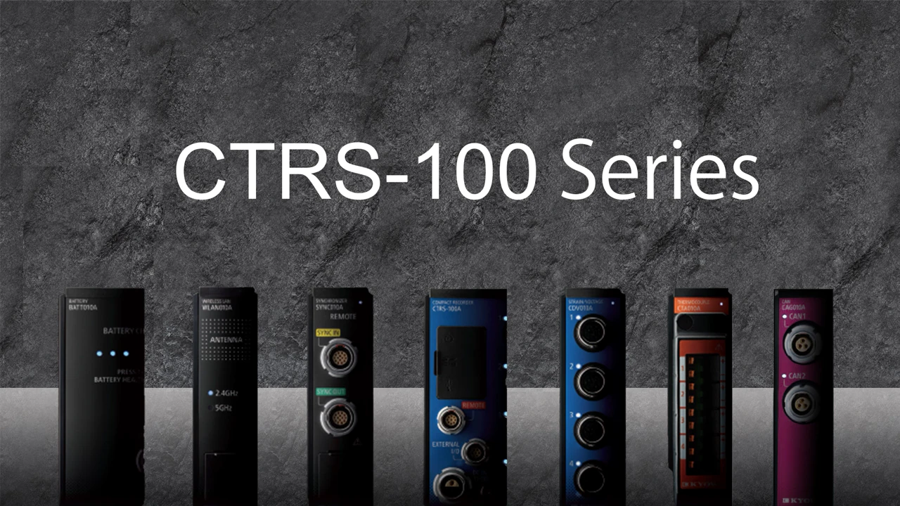
CTRS-100 Series
Compact Recorder
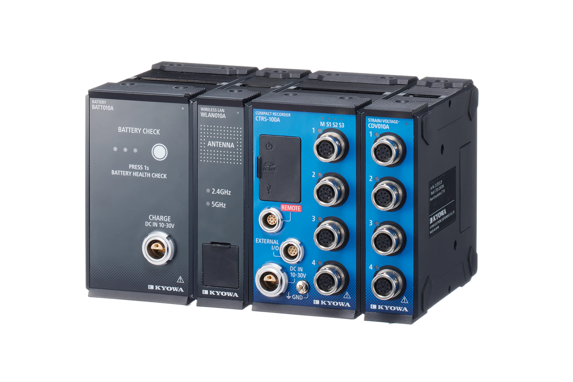
· Modular type for easy expansion and up to 128 channels · High installation and flexibility · Shock resistance: 490 m/s² (50 G) · All channels synchronous 20 kHz (For 4 channels) Measurement of 1 channel at max. 100 kHz · Wireless real-time monitoring is possible (When using wireless LAN unit) · CAN FD compatible (When using CAN unit)
View details in the General CatalogMeasurement Testing Using on-board Network Information (CAN FD)
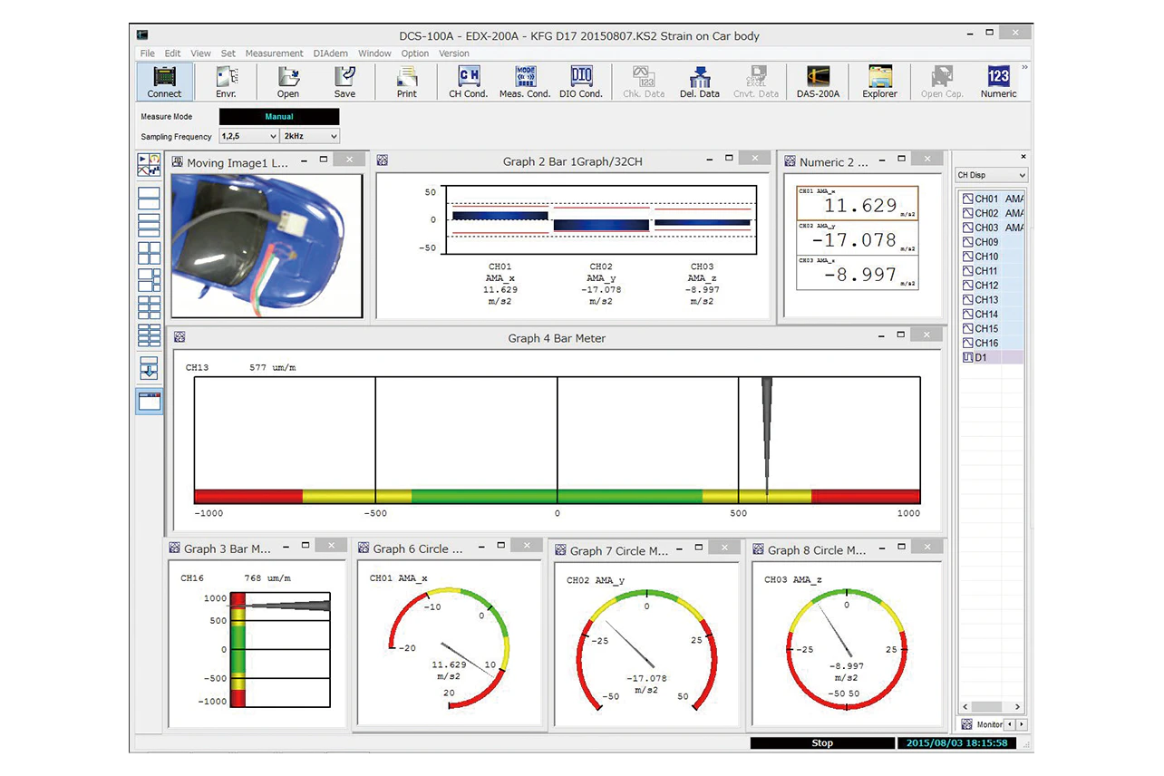
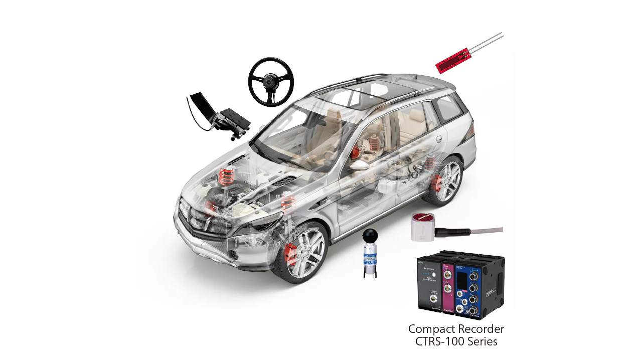
CTRS-100 Series devices can be used to record on-board network information (CAN FD) between ECUs, simultaneously with measurement data from sensors including strain, voltage, and thermocouple (temperature) sensors. Waveforms can even be compared on the screen in software, allowing for more advanced tests to be performed. It also offers excellent impact resistance and vibration resistance, so that testing can be performed in various environments.
On-board Battery Safety Evaluations
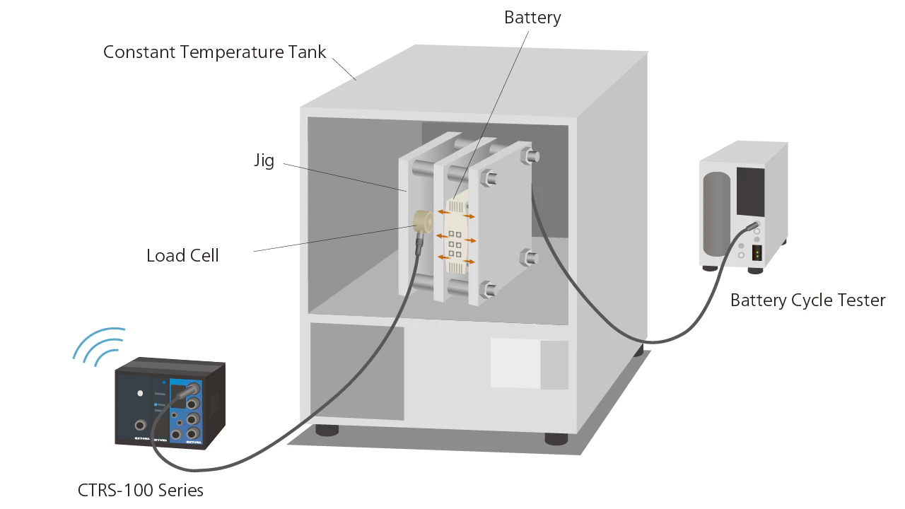
CTRS-100 Series devices can be used with a load cell to evaluate safety, such as using load to measure expansion caused by battery deterioration. We also offer a lineup of products that are compact and resistant to high temperatures, to support a wide range of test conditions including charge/discharge testing in constant temperature tanks.
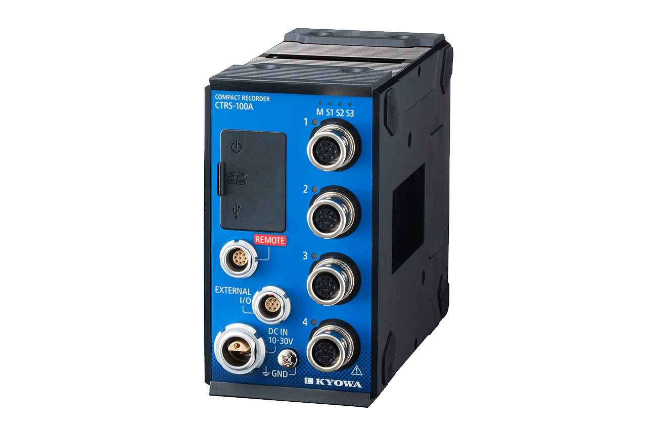
- CTRS-100A Compact Recorder
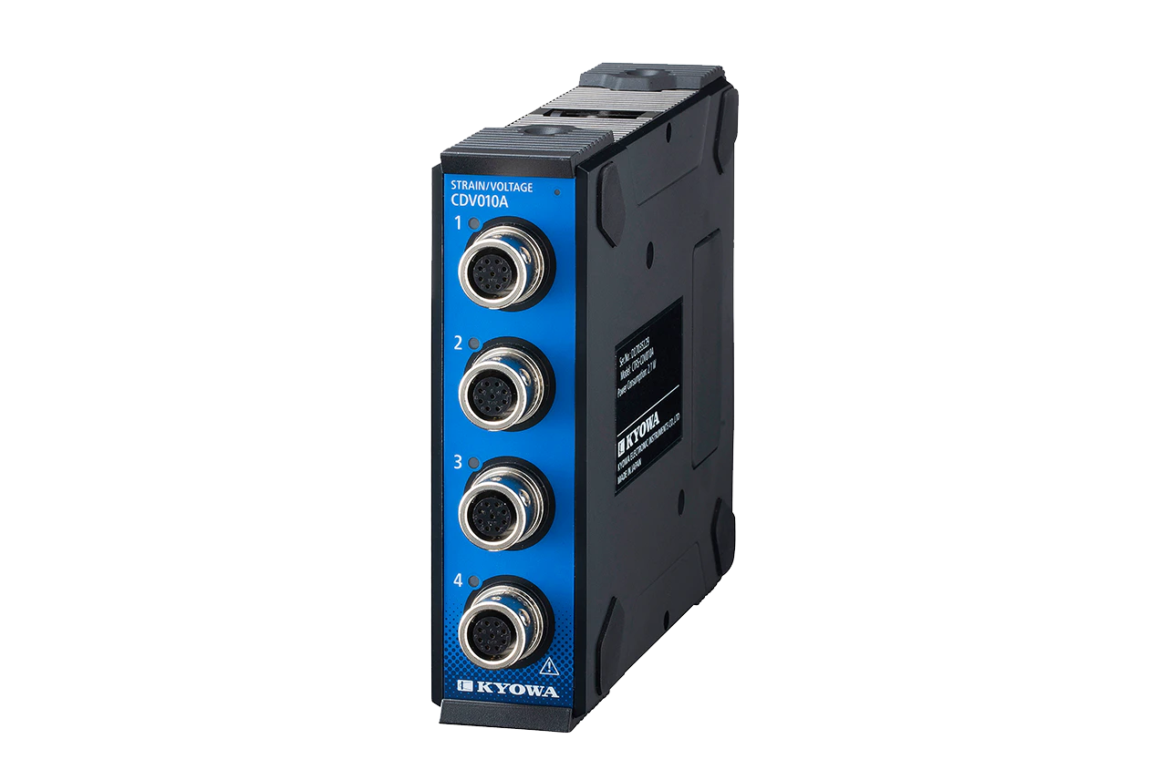
- CTRS-CDV010A Strain/Voltage Unit
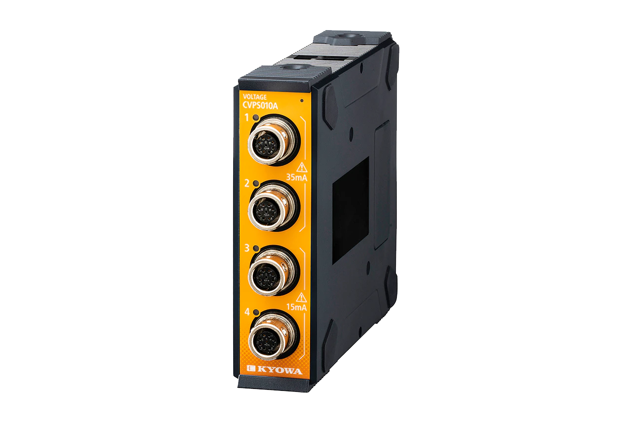
- CTRS-CVPS010A Voltage Unit
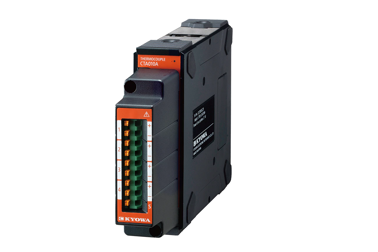
- CTRS-CTA010A Thermocouple Unit
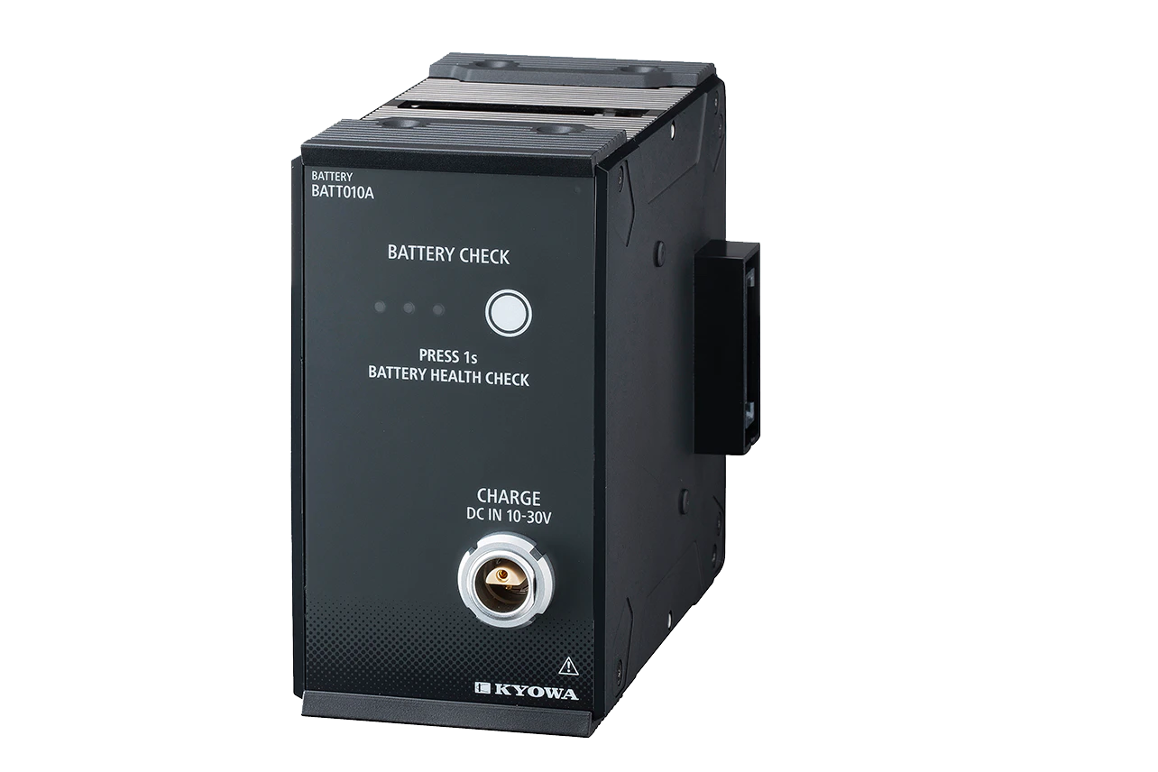
- CTRS-BATT010A Battery Unit
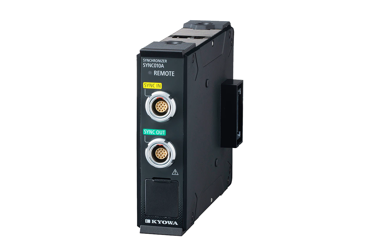
- CTRS-SYNC010A Synchronization Unit
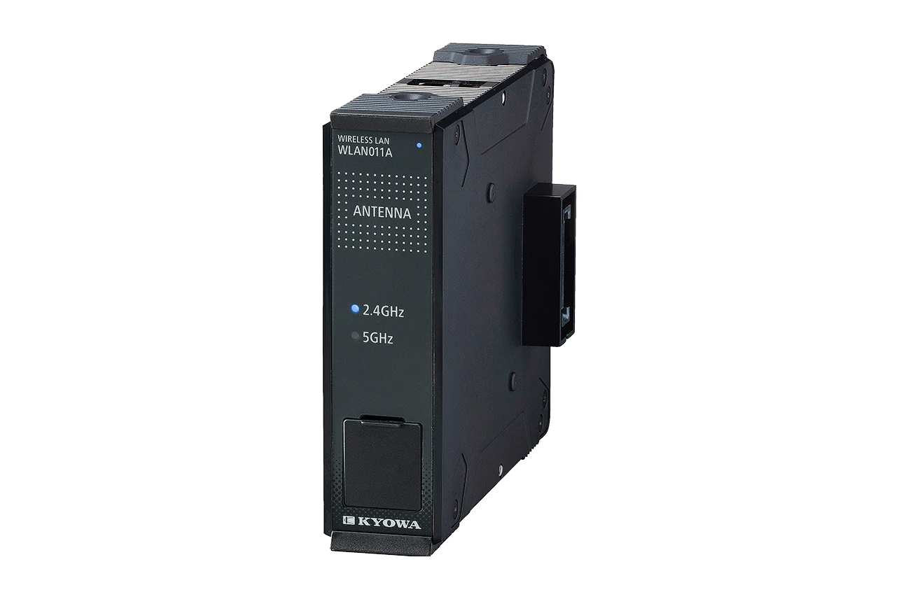
- CTRS-WLAN011A Wireless LAN Unit for United States
- CTRS-WLAN012A Wireless LAN Unit for Thailand, EU
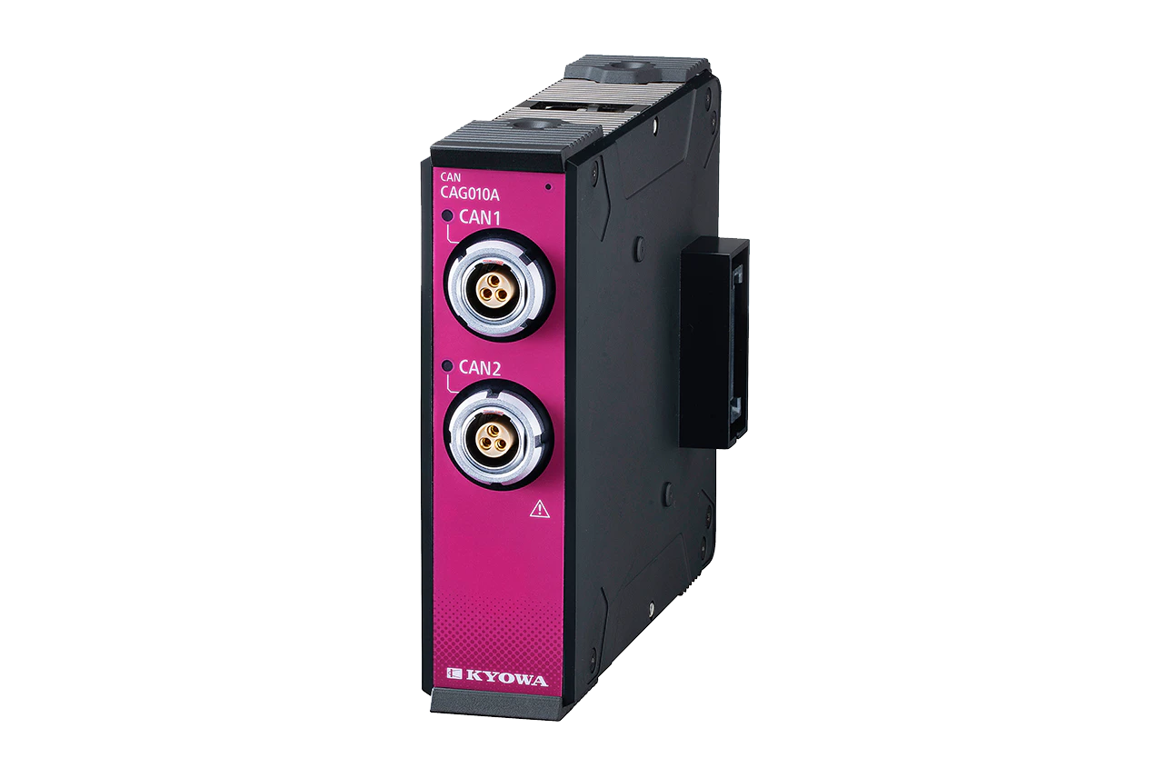
- CTRS-CAG010A CAN Unit
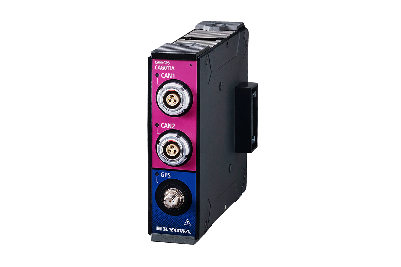
- CTRS-CAG011A CAN/GPS Unit
CTRS-100 Series
CTRS-100A Compact Recorder
CTRS-100 Series
CTRS-CDV010A Strain/Voltage Unit
CTRS-100 Series
CTRS-CVPS010A Voltage Unit
CTRS-100 Series
CTRS-CTA010A Thermocouple Unit
CTRS-100 Series
CTRS-BATT010A Battery Unit
CTRS-100 Series
CTRS-SYNC010A Synchronization Unit
CTRS-100 Series
CTRS-WLAN011A Wireless LAN Unit for United States
CTRS-100 Series
CTRS-WLAN012A Wireless LAN Unit for Thailand, EU
CTRS-100 Series
CTRS-CAG010A CAN Unit
CTRS-100 Series
CTRS-CAG011A CAN/GPS Unit
Catalogs
Manual
- CTRS-100A INSTRUCTION MANUAL for HARDWARE(9.2 MB)
- CTRS-100A INSTRUCTION MANUAL FOR CONTROL COMMAND(4.3 MB)
- CTRS-100A UPDATE SOFTWARE(928 KB)
- CTRS-100A READ BEFORE USING(660 KB)
- CTRS-RCU010A READ BEFORE USING(437 KB)
- CTRS-CDV010A READ BEFORE USING(437 KB)
- CTRS-CTA010A READ BEFORE USING(508 KB)
- CTRS-CVPS010A READ BEFORE USING(719 KB)
- CTRS-SYNC010A READ BEFORE USING(654 KB)
- CTRS-BATT010A READ BEFORE USING(665 KB)
- CTRS-WLAN010A READ BEFORE USING(730 KB)
- CTRS-CAG010A READ BEFORE USING(1.6 MB)
- CTRS-CAG011A READ BEFORE USING(521 KB)
- CTRS-100A NETWORK UTILITY SOFTWARE(790 KB)
- CTRS-100A INSTRUCTION MANUAL for Control DLL Manual(1.9 MB)
Software
Videos related to this products
Main Compatible Accessories
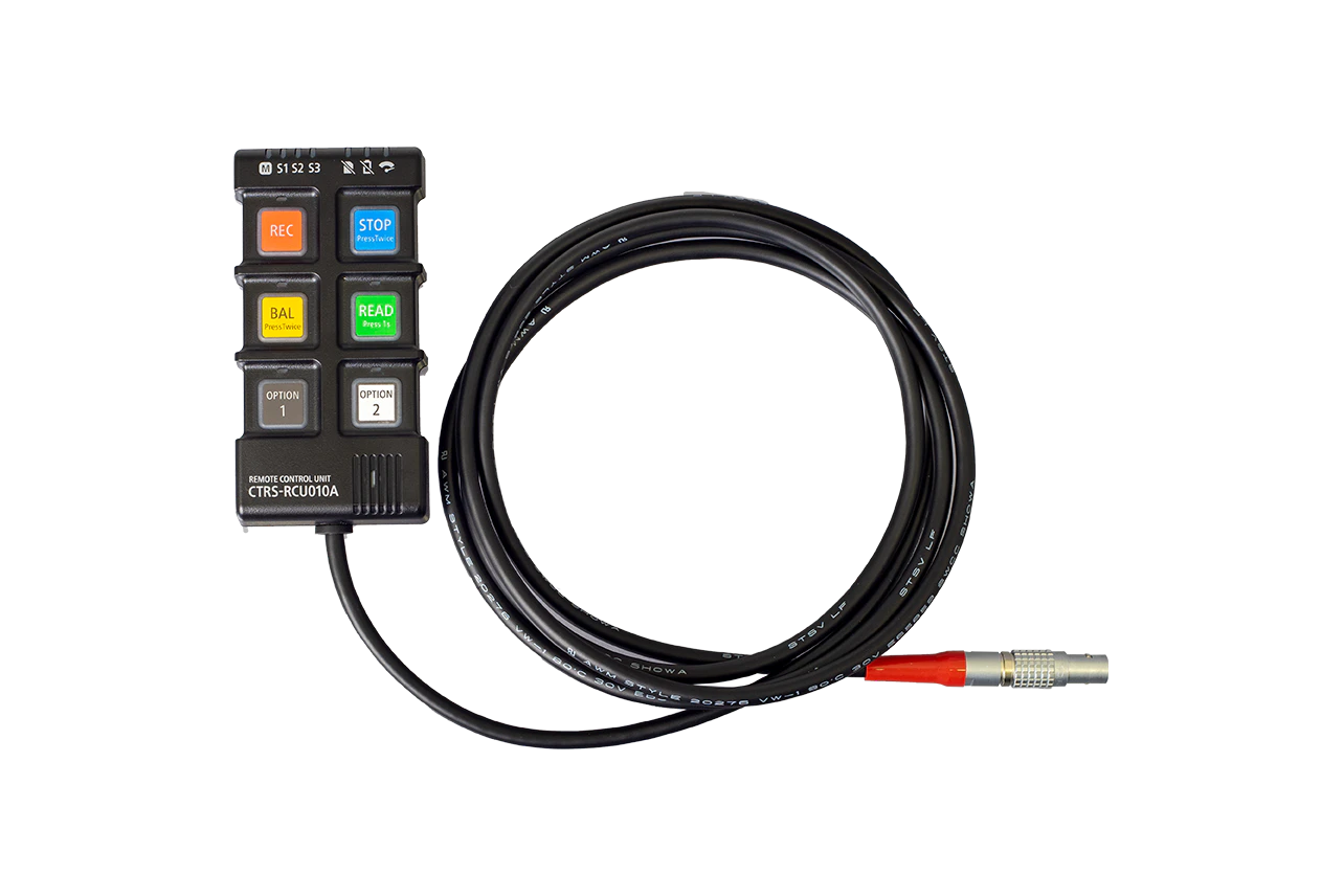
Remote Control Unit
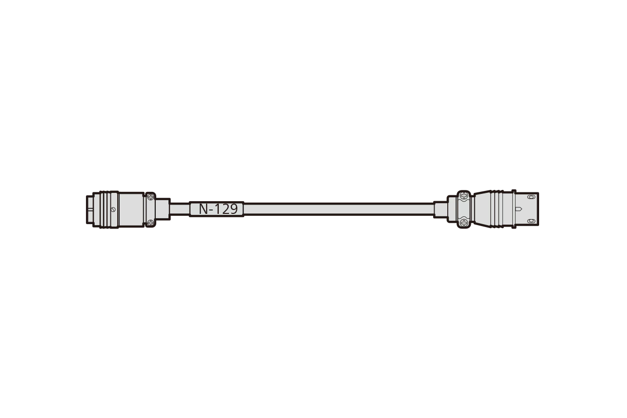
4109P to S32-7
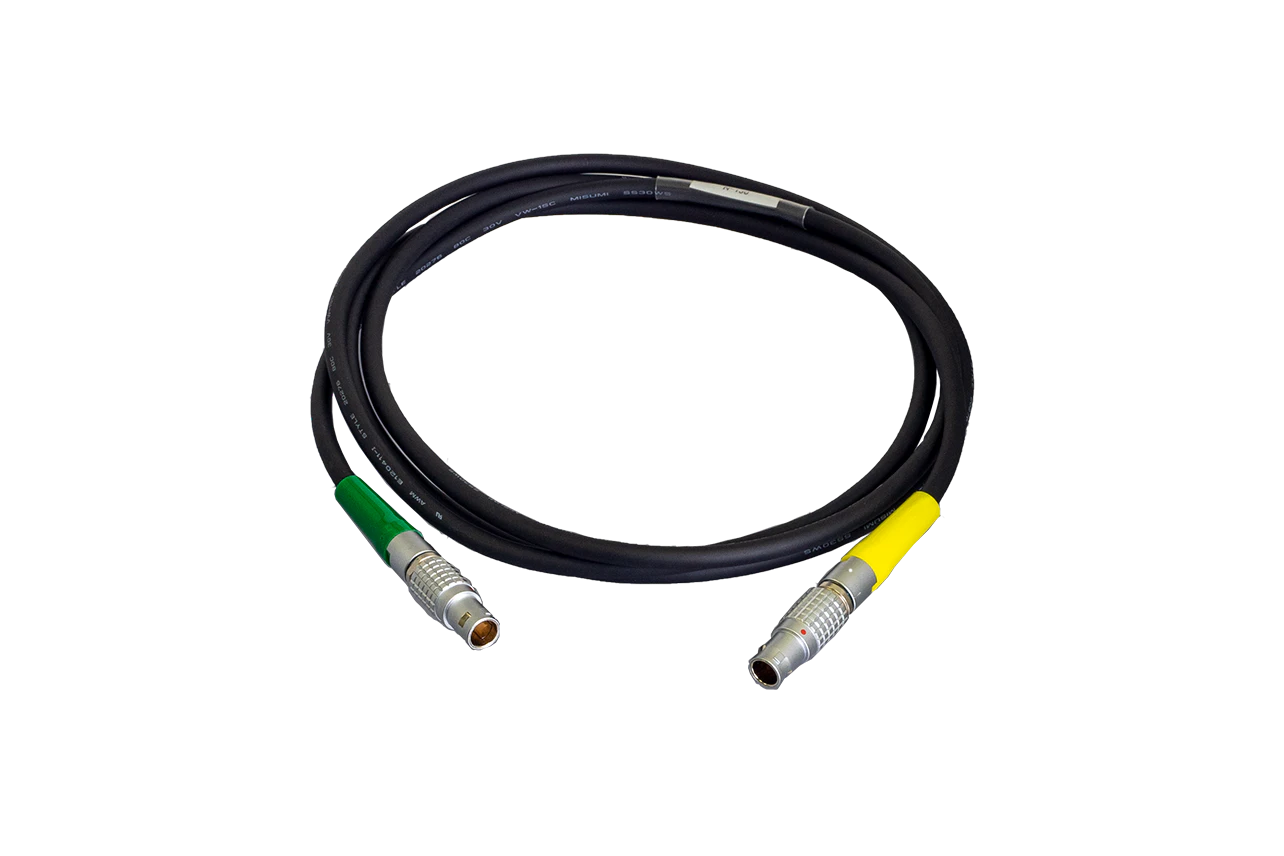
14-pin LEMO connector to 14-pin LEMO connector

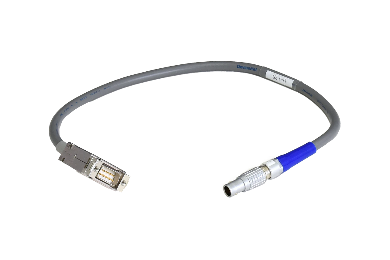
14-pin LEMO connector to RJ-45
2-pin plug to 2-pin receptacle

2-pin LEMO connector to 2 conductors, pre-soldering at the cable tip
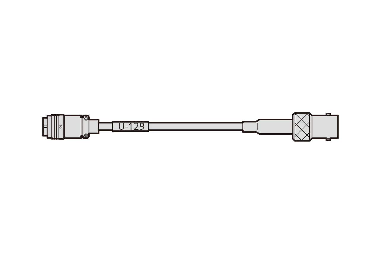
4109P to BNC jack
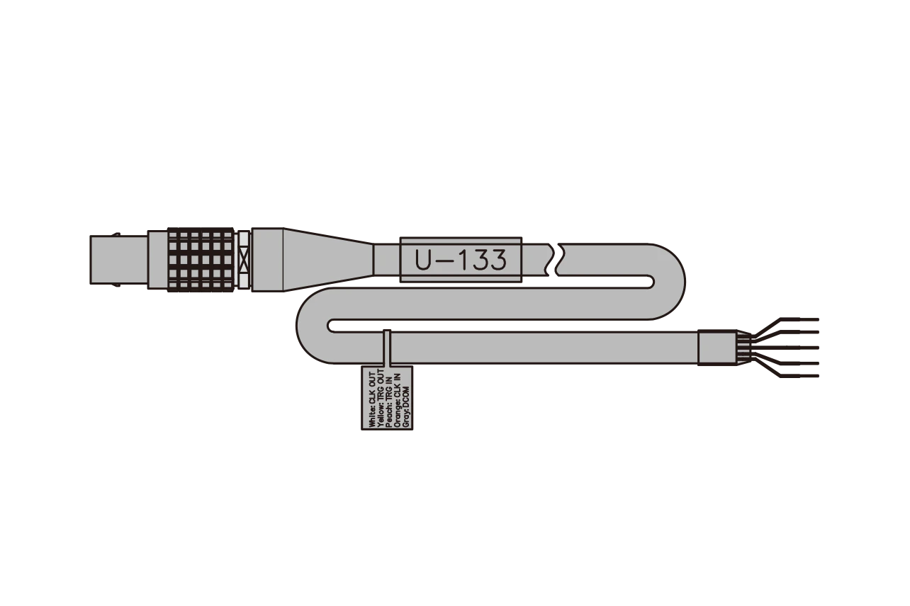
7-pin LEMO connector to 4 conductors with shield wire, bared at the tip
LEMO connector to 9-pin male D-sub
4109P to S32-7
4109P to BNC plug
4109P to R05 jack
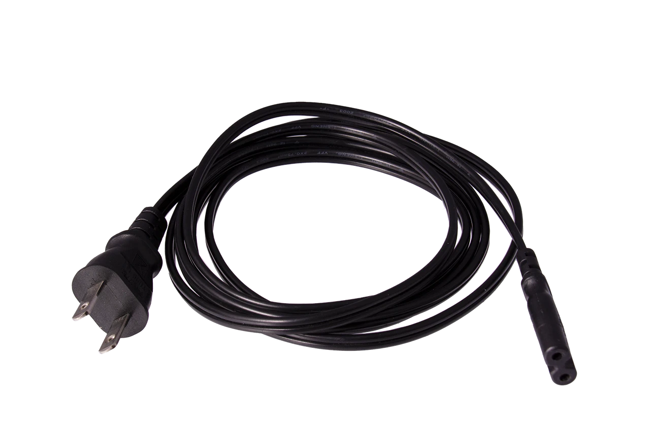
AC adapter