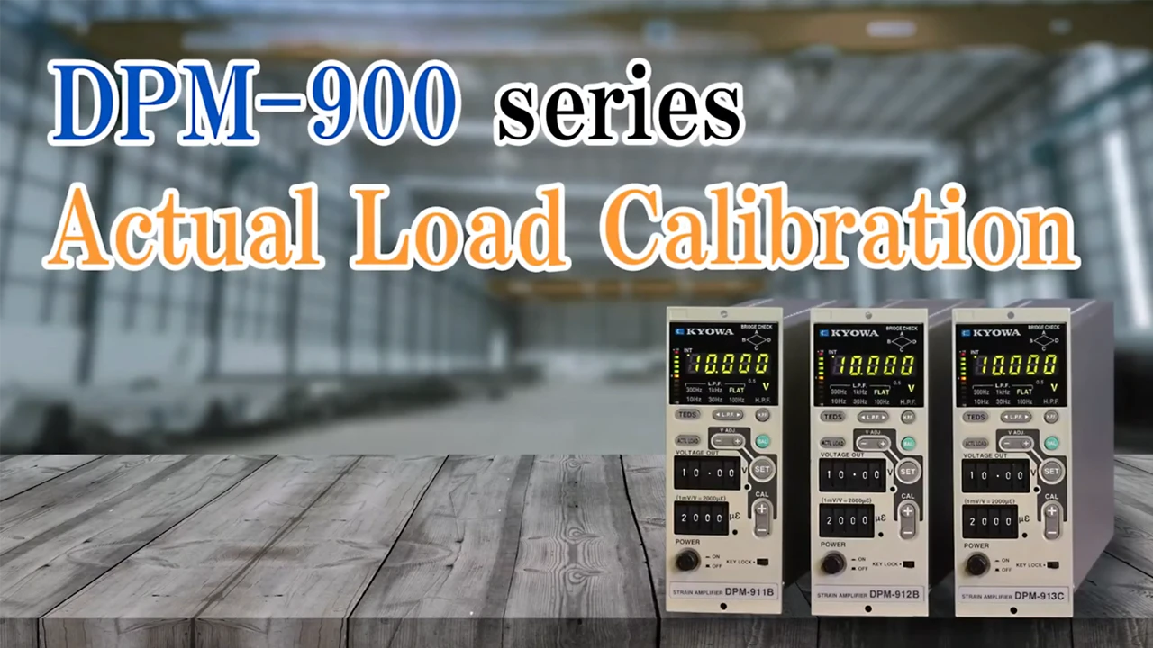
DPM-900 Series
Strain Amplifier

Summary
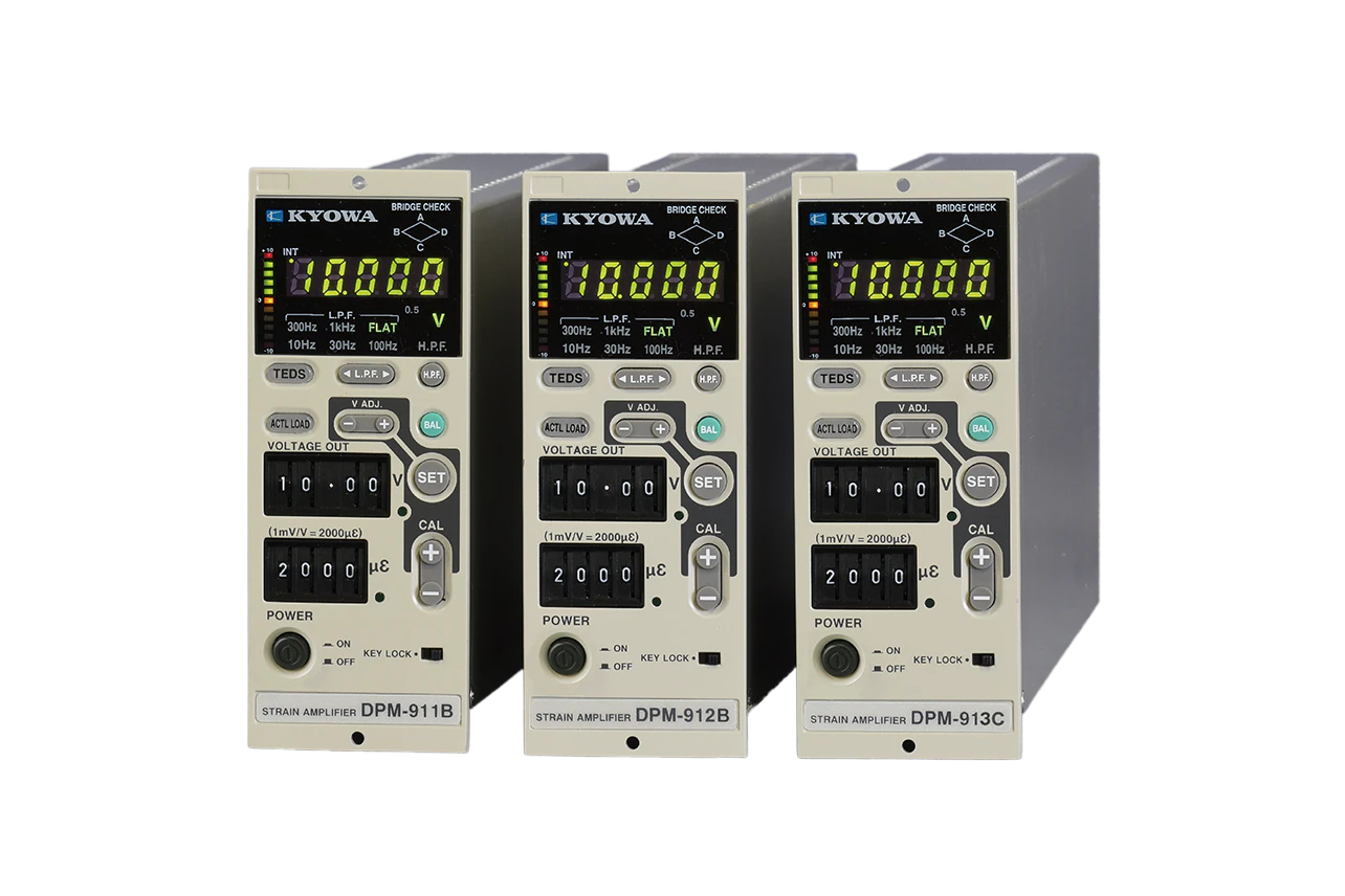
· Built-in HPF cancels the effect of temperature drift
· Digital switch makes it easily to confirm the setting values even power off.
· High voltage output of ±10 V and high SN ratio
· Broad frequency response DC to 10 k Hz (913C)
Features
The DPM-900 Series is a Dynamic Strain Amplifier. The carrier-wave amplifier features highly accurate, excellent stable, and easy setting.
Relative images

Products table
All display
DPM-911B
Frequency Response: DC to 2.5 kHz

Specifications
Carrier Wave Frequencies | 5 kHz |
---|---|
Measuring Targets | Strain gages, strain-gage transducers |
Channels | 1 Simultaneous operation is available by using multiple units. |
Compatible Bridge Resistance | 60 to 1000 Ω |
Gage Factor | 2.00 fixed |
Bridge Excitation | 2 Vrms, 0.5 Vrms, switchable |
Balance Adjustment | Resistance: Within ±2% (±10000 ×10-6 strain) Capacity: Within 2000 pF |
Balance Adjustment Method | Resistance: Auto balance Accuracy: Within ±0.5 ×10⁻⁶ strain (When 500 ×10-6 strain is input, outputs 10 V, excitation voltage: 2 Vrms) Storage: Written into nonvolatile memory Capacitance: CST method (Capacitance self-tracking) |
Nonlinearity | Within ±0.1% FS |
Output Impedance | Approx. 2 Ω |
Calibration Strain (CAL) | Within ±(1 to 9999 ×10-6 strain) by 1 ×10⁻⁶ strain step Setting: CAL switch (4-digital switch) Accuracy: Within ±(0.5% +0.5 ×10⁻⁶ strain) Applicable scope of CAL accuracy: ±(10 to 9999) ×10-6 strain |
Sensitivity Adjustment | Sensitivity is set in combination with CAL and VOLTAGE OUT switches (4-digit digital switches). CAL switch range: 100 to 9999 ×10-6 strain by 1 ×10⁻⁶ strain step VOLTAGE OUT switch range: 1.00 to 10.00 by 0.01 V step [Condition] When 500 ×10-6 strain is input, outputs 10.00 V (× 20000) When 5000 ×10-6 strain is input, outputs 1.00 V (× 200) [Setting example] When 500 is set to CAL, VOLTAGE OUT is 10.00 V (× 20000) When 5000 is set to CAL, VOLTAGE OUT is 1.00 V (× 200) Accuracy: Within ±0.5% (When bridge power supply is 2 Vrms) |
Fine Sensitivity Adjustment | Range: 1 to 1/2.5 |
Frequency Response | DC to 2.5 kHz Deviation: ±10% |
LPF | Transfer characteristic : 2nd order Butterworth Cutoff frequencies : 10, 30, 100, 300 Hz, 1k Hz, and FLAT - 6 steps Amplitude ratio at cutoff point : -3 ±1 dB Attenuation : -12 ±1 dB/oct. (Except when DPM-911B is set to 1 kHz) |
HPF | Cutoff frequencies : 0.2 Hz, OFF- 2 steps |
SN Ratio | 54 dBp-p or more (RTI: Within 2 ×10⁻⁶ strainp-p) (When 500 ×10-6 strain is input, outputs 10.00 V.) 60 dBp-p or more (When 1000 ×10-6 strain is input, outputs 10.00 V.) [Common condition] Excitation voltage: 2 Vrms Bridge resistance: 120 Ω, LPF = FLAT |
Output | OUTPUT A : ±10 V (Load resistance 5 kΩ or more) OUTPUT B : ±10 V (Load resistance 5 kΩ or more) |
Stability | Temperature Zero point: Within ±0.1 ×10⁻⁶ strain per °C Sensitivity: Within ±0.05%/ºC Time Zero point: Within ±0.5 ×10⁻⁶ strain/24 h Sensitivity: Within ±0.3%/24 h Power supply Zero point: Within ±0.05% FS/power fluctuation ±10% Sensitivity: Within ±0.05%/power fluctuation ±10% |
Withstand Voltage | 1000 VAC for 1 minute between measuring bridge and case 1000 VAC for 1 minute between AC power supply and case |
Output Voltage Indication | 4½ digit digital display (7-segment LED) 11-segment LED bar meter |
Over Input Indication | Output voltage display flashing (4½ digit digital display only) |
Check Functions | Bridge check |
Key Lock Functions | Locks all keys other than POWER switch. (Allows settings on CAL and VOLTAGE OUT switches to be changed.) |
Remote Functions | Capable of controlling the following functions. Balance adjustment execute (BAL) Calibration strain output execute (CAL) Key lock |
Synchronization Method | Automatically determines internal (INT) or external (EXT) and manual setting. |
TEDS | Reads the sensor TEDS information, and sets the rated output to the VOLTAGE OUT output voltage. (Condition: Within the setting range of the sensitivity adjuster) |
Actual Load Calibration | Sets actual load input to the VOLTAGE OUT output voltage. (Condition: Within the setting range of the sensitivity adjuster) |
Vibration Resistant | 5 to 200 Hz, with 29.4 m/s2 (3 G) in X, Y and Z directions for 12 cycles, 10 min/cycle |
Impact Resistant | 15 G, 11 ms or less, in X, Y and Z directions, every 3 cycles |
Operating Temperature | -10 to 50°C |
Operating Humidity | 20 to 85% (Non-condensing) |
Storage Temperature | -30 to 70°C |
Power Supply | 90 to 110 VAC (Approx. 12 VA: 100 VAC) 10.5 to 15 VDC (Approx. 0.6 A: 12 VDC) Following models are also available. DPM-xxxx A115: 108 to 132 VAC DPM-xxxx A200: 180 to 220 VAC DPM-xxxx A230: 207 to 253 VAC xxxx: Part of model, example; 911B |
Dimensions | 49 W ×128.5 H ×262.5 D mm (Excluding protrusions) Panel-cut dimensions: 50 W ×113 H mm |
Weight | Approx. 1.2 kg |
Standard Accessories | Output cable U-08, U-59, 1 each AC power cable P-25 (With 2-pin conversion plug CM-52) Fuse (Midget type 0.5 A, 1 A) Instruction manual Simple manual sticker |
---|---|
Optional Accessories | Extension cables N-81 to N-85 Bridge boxes DB, DBB, and DBS Housing case YC-A Noise filter F-7B, F-BNC Amplifier stand FA-1B Shielded conversion cable N-117 |
Dimensions

DPM-912B
Frequency Response: DC to 5 kHz

Specifications
Carrier Wave Frequencies | 12 kHz |
---|---|
Measuring Targets | Strain gages, strain-gage transducers |
Channels | 1 Simultaneous operation is available by using multiple units. |
Compatible Bridge Resistance | 60 to 1000 Ω |
Gage Factor | 2.00 fixed |
Bridge Excitation | 2 Vrms, 0.5 Vrms, switchable |
Balance Adjustment | Resistance: Within ±2% (±10000 ×10-6 strain) Capacity: Within 2000 pF |
Balance Adjustment Method | Resistance: Auto balance Accuracy: Within ±0.5 ×10⁻⁶ strain (When 500 ×10-6 strain is input, outputs 10 V, excitation voltage: 2 Vrms) Storage: Written into nonvolatile memory Capacitance: CST method (Capacitance self-tracking) |
Nonlinearity | Within ±0.1% FS |
Output Impedance | Approx. 2 Ω |
Calibration Strain (CAL) | Within ±(1 to 9999 ×10-6 strain) by 1 ×10⁻⁶ strain step Setting: CAL switch (4-digital switch) Accuracy: Within ±(0.5% +0.5 ×10⁻⁶ strain) Applicable scope of CAL accuracy: ±(10 to 9999) ×10-6 strain |
Sensitivity Adjustment | Sensitivity is set in combination with CAL and VOLTAGE OUT switches (4-digit digital switches). CAL switch range: 100 to 9999 ×10-6 strain by 1 ×10⁻⁶ strain step VOLTAGE OUT switch range: 1.00 to 10.00 by 0.01 V step [Condition] When 500 ×10-6 strain is input, outputs 10.00 V (× 20000) When 5000 ×10-6 strain is input, outputs 1.00 V (× 200) [Setting example] When 500 is set to CAL, VOLTAGE OUT is 10.00 V (× 20000) When 5000 is set to CAL, VOLTAGE OUT is 1.00 V (× 200) Accuracy: Within ±0.5% (When bridge power supply is 2 Vrms) |
Fine Sensitivity Adjustment | Range: 1 to 1/2.5 |
Frequency Response | DC to 5 kHz Deviation: ±10% |
LPF | Transfer characteristic : 2nd order Butterworth Cutoff frequencies : 10, 30, 100, 300 Hz, 1k Hz, and FLAT - 6 steps Amplitude ratio at cutoff point : -3 ±1 dB Attenuation : -12 ±1 dB/oct. |
HPF | Cutoff Frequencies : 0.2 Hz, OFF- 2 steps |
SN Ratio | 52 dBp-p or more (RTI: Within 2.5 ×10⁻⁶ strainp-p) (When 500 ×10-6 strain is input, outputs 10.00 V.) 57 dBp-p or more (When 1000 ×10-6 strain is input, outputs 10.00 V.) [Common condition] Excitation voltage: 2 Vrms Bridge resistance: 120 Ω, LPF = FLAT |
Output | OUTPUT A: ±10 V (Load resistance 5 kΩ or more) OUTPUT B: ±10 V (Load resistance 5 kΩ or more) |
Stability | Temperature Zero point: Within ±0.1 ×10⁻⁶ strain per °C Sensitivity: Within ±0.05%/ºC Time Zero point: Within ±0.5 ×10⁻⁶ strain/24 h Sensitivity: Within ±0.3%/24 h Power supply Zero point: Within ±0.05% FS/power fluctuation ±10% Sensitivity: Within ±0.05%/power fluctuation ±10% |
Withstand Voltage | 1000 VAC for 1 minute between measuring bridge and case 1000 VAC for 1 minute between AC power supply and case |
Output Voltage Indication | 4½ digit digital display (7-segment LED) 11-segment LED bar meter |
Over Input Indication | Output voltage display flashing (4½ digit digital display only) |
Check Functions | Bridge check |
Key Lock Functions | Locks all keys other than POWER switch. (Allows settings on digital CAL and VOLTAGE OUT switches to be changed.) |
Remote Functions | Capable of controlling the following functions. Balance adjustment execute (BAL) Calibration strain output execute (CAL) Key lock |
Synchronization Method | Automatically determines internal (INT) or external (EXT) and manual setting. |
TEDS | Reads the sensor TEDS information, and sets the rated output to the VOLTAGE OUT output voltage. (Condition: Within the setting range of the sensitivity adjuster) |
Actual Load Calibration | Sets actual load input to the VOLTAGE OUT output voltage. (Condition: Within the setting range of the sensitivity adjuster) |
Vibration Resistant | 5 to 200 Hz, with 29.4 m/s2 (3 G) in X, Y and Z directions for 12 cycles, 10 min/cycle |
Impact Resistant | 15 G, 11 ms or less, in X, Y and Z directions, every 3 cycles |
Operating Temperature | -10 to 50°C |
Operating Humidity | 20 to 85% (Non-condensing) |
Storage Temperature | -30 to 70°C |
Power Supply | 90 to 110 VAC (Approx. 12 VA: 100 VAC) 10.5 to 15 VDC (Approx. 0.6 A: 12 VDC) Following models are also available. DPM-xxxx A115: 108 to 132 VAC DPM-xxxx A200: 180 to 220 VAC DPM-xxxx A230: 207 to 253 VAC xxxx: Part of model, example; 912B |
Dimensions | 49 W ×128.5 H ×262.5 D mm (Excluding protrusions) Panel-cut dimensions: 50 W ×113 H mm |
Weight | Approx. 1.2 kg |
Standard Accessories | Output cable U-08, U-59, 1 each AC power cable P-25 (With 2-pin conversion plug CM-52) Fuse (Midget type 0.5 A, 1 A) Instruction manual Simple manual sticker |
---|---|
Optional Accessories | Extension cables N-81 to N-85 Bridge boxes DB, DBB, and DBS Housing case YC-A Noise filter F-7B, F-BNC Amplifier stand FA-1B Shielded conversion cable N-117 |
DPM-913C
Frequency Response: DC to 10 kHz

Specifications
Carrier Wave Frequencies | 28 kHz |
---|---|
Measuring Targets | Strain gages, strain-gage transducers |
Channels | 1 Simultaneous operation is available by using multiple units. |
Compatible Bridge Resistance | 60 to 1000 Ω |
Gage Factor | 2.00 fixed |
Bridge Excitation | 2 Vrms, 0.5 Vrms, switchable |
Balance Adjustment | Resistance: Within ±2% (±10000 ×10-6 strain) Capacity: Within 2000 pF |
Balance Adjustment Method | Resistance: Auto balance Accuracy: Within ±0.5 ×10⁻⁶ strain (When 500 ×10-6 strain is input, outputs 10 V, excitation voltage: 2 Vrms) Storage: Written into nonvolatile memory Capacitance: CST method (Capacitance self-tracking) |
Nonlinearity | Within ±0.2% FS |
Output Impedance | Approx. 2 Ω |
Calibration Strain (CAL) | Within ±(1 to 9999 ×10-6 strain) by 1 ×10⁻⁶ strain step Setting: CAL switch (4-digital switch) Accuracy: Within ±(0.5% +1 ×10⁻⁶ strain) Applicable scope of CAL accuracy: ±(10 to 9999) ×10-6 strain |
Sensitivity Adjustment | Sensitivity is set in combination with CAL and VOLTAGE OUT switches (4-digit digital switches). CAL switch range: 100 to 9999 ×10-6 strain by 1 ×10⁻⁶ strain step VOLTAGE OUT switch range: 1.00 to 10.00 by 0.01 V step [Condition] When 500 ×10-6 strain is input, outputs 10.00 V (× 20000) When 5000 ×10-6 strain is input, outputs 1.00 V (× 200) [Setting example] When 500 is set to CAL, VOLTAGE OUT is 10.00 V (× 20000) When 5000 is set to CAL, VOLTAGE OUT is 1.00 V (× 200) Accuracy: Within ±0.5% |
Fine Sensitivity Adjustment | Range: 1 to 1/2.5 |
Frequency Response | DC to 10 kHz Deviation: ±10% |
LPF | Transfer characteristic : 2nd order Butterworth Cutoff frequencies : 10, 30, 100, 300 Hz, 1k Hz and FLAT - 6 steps Amplitude ratio at cutoff point : -3 ±1 dB Attenuation : -12 ±1 dB/oct. |
HPF | Cutoff Frequencies : 0.2 Hz, OFF- 2 steps |
SN Ratio | 48 dBp-p or more (RTI: Within 3.9 ×10⁻⁶ strainp-p) (When 500 ×10-6 strain is input, outputs 10.00 V.) 53 dBp-p or more (When 1000 ×10-6 strain is input, outputs 10.00 V.) [Common condition] Excitation voltage: 2 Vrms Bridge resistance: 120 Ω, LPF = FLAT |
Output | OUTPUT A: ±10 V (Load resistance 5 kΩ or more) OUTPUT B: ±10 V (Load resistance 5 kΩ or more) |
Stability | Temperature Zero point: Within ±0.2 ×10⁻⁶ strain per °C Sensitivity: Within ±0.05%/ºC Time Zero point: Within ±1.0 ×10⁻⁶ strain/24 h Sensitivity: Within ±0.3%/24 h Power supply Zero point: Within ±0.05% FS/power fluctuation ±10% Sensitivity: Within ±0.05%/power fluctuation ±10% |
Withstand Voltage | 1000 VAC for 1 minute between measuring bridge and case 1000 VAC for 1 minute between AC power supply and case |
Output Voltage Indication | 4½ digit digital display (7-segment LED) 11-segment LED bar meter |
Over Input Indication | Output voltage display flashing (4½ digit digital display only) |
Check Functions | Bridge check |
Input Open Detection Function | When the input is open, output saturates to the negative side. |
Key Lock Functions | Locks all keys other than POWER switch. (Allows settings on digital CAL and VOLTAGE OUT switches to be changed.) |
Remote Functions | Capable of controlling the following functions. Balance adjustment execute (BAL) Calibration strain output execute (CAL) Key lock |
Synchronization Method | Automatically determines internal (INT) or external (EXT) and manual setting. |
TEDS | Reads the sensor TEDS information, and sets the rated output to the VOLTAGE OUT output voltage. (Condition: Within the setting range of the sensitivity adjuster) |
Actual Load Calibration | Sets actual load input to the VOLTAGE OUT output voltage. (Condition: Within the setting range of the sensitivity adjuster) |
Vibration Resistant | 5 to 200 Hz, with 29.4 m/s2 (3 G) in X, Y and Z directions for 12 cycles, 10 min/cycle |
Impact Resistant | 15 G, 11 ms or less, in X, Y and Z directions, every 3 cycles |
Operating Temperature | -10 to 50ºC |
Operating Humidity | 20 to 85 % (Non-condensing) |
Power Supply | 90 to 110 VAC (Approx. 12 VA: 100 VAC) 10.5 to 15 VDC (Approx. 0.6 A: 12 VDC) Following models are also available. DPM-xxxx A115: 108 to 132 VAC DPM-xxxx A200: 180 to 220 VAC DPM-xxxx A230: 207 to 253 VAC xxxx: Part of model, example; 913C |
Dimensions | 49 W ×128.5 H ×262.5 D mm (Excluding protrusions) Panel-cut dimensions: 50 W ×113 H mm |
Weight | Approx. 1.2 kg |
Standard Accessories | Output cable U-08, U-59, 1 each AC power cable P-25 (With 2-pin conversion plug CM-52) Fuse (Midget type 0.5 A, 1 A) Instruction manual Simple manual sticker |
---|---|
Optional Accessories | Extension cables N-81 to N-85 Bridge boxes DB, DBB, and DBS Housing case YC-A Noise filter F-7B, F-BNC Amplifier stand FA-1B Shielded conversion cable N-117 |